Mitsubishi Montero Sport (2004+). Manual - part 255


  Index      Mitsubishi     Mitsubishi Montero Sport - service repair manual 2004 year


Search            


Content   ..  253  254  255  256   ..


Mitsubishi Montero Sport (2004+). Manual - part 255


MULTIPORT FUEL INJECTION (MFI) DIAGNOSIS

TSB Revision

MULTIPORT FUEL INJECTION (MFI)

13A-433

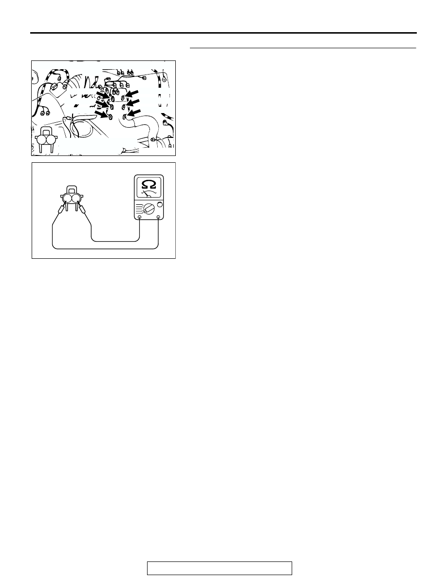
STEP 5. Check the injector.
(1) Disconnect the injector connector A-75 <No. 1 cylinder> or 

A-72 <No. 2 cylinder> or A-74 <No. 3 cylinder> or A-71 
<No. 4 cylinder> or A-73 <No. 5 cylinder> or A-70 <No. 6 
cylinder>.

(2) Measure the resistance between injector side connector 

terminal No. 1 and No. 2.

Standard value: 13 

 16 ohms [at 20°C (68°F)]

Q: Is the resistance between 13 and 16 ohms [at 20

°

(68

°F)]?

YES : Repair harness wire between injector intermediate 

connector and injector connector because of open 
circuit or short circuit to ground or harness 
damage.

a. Repair harness wire between injector 

intermediate connector A-04 (terminal No. 8) 
and injector connector A-75 (terminal No. 1) 
and harness wire between injector connector 
A-75 (terminal No. 2) and injector intermediate 
connector A-04 (terminal No. 3) when 
checking No. 1 cylinder.

b. Repair harness wire between injector 

intermediate connector A-04 (terminal No. 8) 
and injector connector A-72 (terminal No. 1) 
and harness wire between injector connector 
A-72 (terminal No. 2) and injector intermediate 
connector A-04 (terminal No. 2) when 
checking No. 2 cylinder.

c. Repair harness wire between injector 

intermediate connector A-04 (terminal No. 8) 
and injector connector A-74 (terminal No. 1) 
and harness wire between injector connector 
A-74 (terminal No. 2) and injector intermediate 
connector A-04 (terminal No. 1) when 
checking No. 3 cylinder.

d. Repair harness wire between injector 

intermediate connector A-04 (terminal No. 8) 
and injector connector A-71 (terminal No. 1) 
and harness wire between injector connector 
A-71 (terminal No. 2) and injector intermediate 
connector A-04 (terminal No. 7) when 
checking No. 4 cylinder.

AK200022

1

2

AB

CONNECTORS: A-70, A-71, A-72, A-73, A-74, 
                            A-75

A-70(GR)

A-71(GR)

A-72(GR)

HARNESS CONNECTOR: 
COMPONENT SIDE

A-73(GR)

A-74(GR)

A-75(GR)

AK000456

1 2

INJECTOR SIDE
CONNECTOR

AB

MULTIPORT FUEL INJECTION (MFI) DIAGNOSIS

TSB Revision

MULTIPORT FUEL INJECTION (MFI)

13A-434

e. Repair harness wire between injector 

intermediate connector A-04 (terminal No. 8) 
and injector connector A-73 (terminal No. 1) 
and harness wire between injector connector 
A-73 (terminal No. 2) and injector intermediate 
connector A-04 (terminal No. 6) when 
checking No. 5 cylinder.

f. Repair harness wire between injector 

intermediate connector A-04 (terminal No. 8) 
and injector connector A-70 (terminal No. 1) 
and harness wire between injector connector 
A-70 (terminal No. 2) and injector intermediate 
connector A-04 (terminal No. 5) when 
checking No. 6 cylinder.

Then go to Step 12.

NO :  Replace the injector. Then go to Step 12.

STEP 6. Measure the power supply voltage at injector 
intermediate connector A-04.
(1) Disconnect the connector A-04 and measure at the female 

connector side.

(2) Turn the ignition switch to the "ON" position.

(3) Measure the voltage between terminal No. 8 and ground.

• Voltage should be battery positive voltage.

(4) Turn the ignition switch to the "LOCK" (OFF) position.
Q: Is battery positive voltage (approximately 12 volts) 

present?
YES : 
Go to Step 8.
NO :  Go to Step 7.

AK200014

7

2 1
6 5

4 3
8

CONNECTOR: A-04

AB

FEMALE SIDE 
CONNECTOR

A-04(B)

2

8

5

3

4

1

7

AK000545

6

2

8

5

3

4

1

7

AK000545

6

INJECTOR INTERMEDIATE
FEMALE SIDE CONNECTOR

AB

MULTIPORT FUEL INJECTION (MFI) DIAGNOSIS

TSB Revision

MULTIPORT FUEL INJECTION (MFI)

13A-435

STEP 7. Check connector C-59 at MFI relay for damage.
Q: Is the connector in good condition?

YES : Check connector C-14 at intermediate connector for 

damage, and repair or replace as required. Refer to 
GROUP 00E, Harness Connector Inspection 

P.00E-2

. If intermediate connector is in good 

condition, repair harness wire between MFI relay 
connector C-59 (terminal No. 1) and injector 
intermediate connector A-04 (terminal No. 8) because 
of open circuit or short circuit to ground. Then go to 
Step 12.

NO :  Repair or replace it. Refer to GROUP 00E, Harness 

Connector Inspection 

P.00E-2

. Then go to Step 12.

STEP 8. Check for harness damage between MFI relay 
connector C-59 (terminal No. 1) and injector intermediate 
connector A-04 (terminal No. 8).
Q: Is the harness wire in good condition?

YES : Go to Step 9.
NO :  Repair it. Then go to Step 12.

AK200023

2 1

3

4

CONNECTOR: C-59

AB

C-59

HARNESS 
CONNECTOR:
COMPONENT 
SIDE

AK200023

2 1

3

4

CONNECTOR: C-59

AB

C-59

HARNESS 
CONNECTOR:
COMPONENT 
SIDE

AK200014

7

2 1
6 5

4 3
8

CONNECTOR: A-04

AB

FEMALE SIDE 
CONNECTOR

A-04(B)

MULTIPORT FUEL INJECTION (MFI) DIAGNOSIS

TSB Revision

MULTIPORT FUEL INJECTION (MFI)

13A-436

STEP 9. Check connector C-89 at PCM for damage.
Q: Is the connector in good condition?

YES : Go to Step 10.
NO :  Repair or replace it. Refer to GROUP 00E, Harness 

Connector Inspection 

P.00E-2

. Then go to Step 12.

STEP 10. Check for open circuit and short circuit to 
ground and harness damage between injector 
intermediate connector and PCM connector.

a. Check the harness wire between intermediate connector 

A-04 (terminal No. 3) and PCM connector C-89 (terminal 
No. 1) when checking No. 1 cylinder.

b. Check the harness wire between intermediate connector 

A-04 (terminal No. 2) and PCM connector C-89 (terminal 
No. 9) when checking No. 2 cylinder.

c. Check the harness wire between intermediate connector 

A-04 (terminal No. 1) and PCM connector C-89 (terminal 
No. 24) when checking No. 3 cylinder.

d. Check the harness wire between intermediate connector 

A-04 (terminal No.7) and PCM connector C-89 (terminal 
No. 2) when checking No. 4 cylinder.

e. Check the harness wire between intermediate connector 

A-04 (terminal No. 6) and PCM connector C-89 (terminal 
No. 10) when checking No. 5 cylinder.

f. Check the harness wire between intermediate connector 

A-04 (terminal No. 5) and PCM connector C-89 (terminal 
No. 25) when checking No. 6 cylinder.

Q: Is the harness wire in good condition?

YES : Go to Step 11.
NO :  Repair it. Then go to Step 12.

AK103914

2

3

4

5

6

7

8

9

11

12

13

14

15

16

17

18

19

20

30

21

22

23

24

25

26

27

28

29

31

32

33

34

35

1

10

AB

CONNECTOR: C-89

C-89(GR)

HARNESS CONNECTOR:
COMPONENT SIDE

AK200014

7

2 1
6 5

4 3
8

CONNECTOR: A-04

AB

FEMALE SIDE 
CONNECTOR

A-04(B)

AK103914

2

3

4

5

6

7

8

9

11

12

13

14

15

16

17

18

19

20

30

21

22

23

24

25

26

27

28

29

31

32

33

34

35

1

10

AB

CONNECTOR: C-89

C-89(GR)

HARNESS CONNECTOR:
COMPONENT SIDE


Content   ..  253  254  255  256   ..