Mitsubishi Montero Sport (2004+). Manual - part 254
MULTIPORT FUEL INJECTION (MFI) DIAGNOSIS
TSB Revision
MULTIPORT FUEL INJECTION (MFI)
13A-429
.
CIRCUIT OPERATION
• The injector power is supplied from the MFI relay
(terminal No. 1).
• The PCM controls the injector by turning the
power transistor in the PCM "ON" and "OFF".
.
TECHNICAL DESCRIPTION
• The amount of fuel injected by the injector is con-
trolled by the amount of continuity time the coil is
grounded by the PCM.
• A surge voltage is generated when the injectors
are driven and the current flowing to the injector
coil is shut off.
• The PCM checks this surge voltage.
.
DESCRIPTIONS OF MONITOR METHODS
Off-surge does not occur after injector is operated.
.
MONITOR EXECUTION
Continuous
.
MONITOR EXECUTION CONDITIONS (Other
monitor and Sensor)
Other Monitor (There is no temporary DTC stored
in memory for the item monitored below)
• Not applicable
Sensor (The sensor below is determined to be
normal)
• Not applicable
.
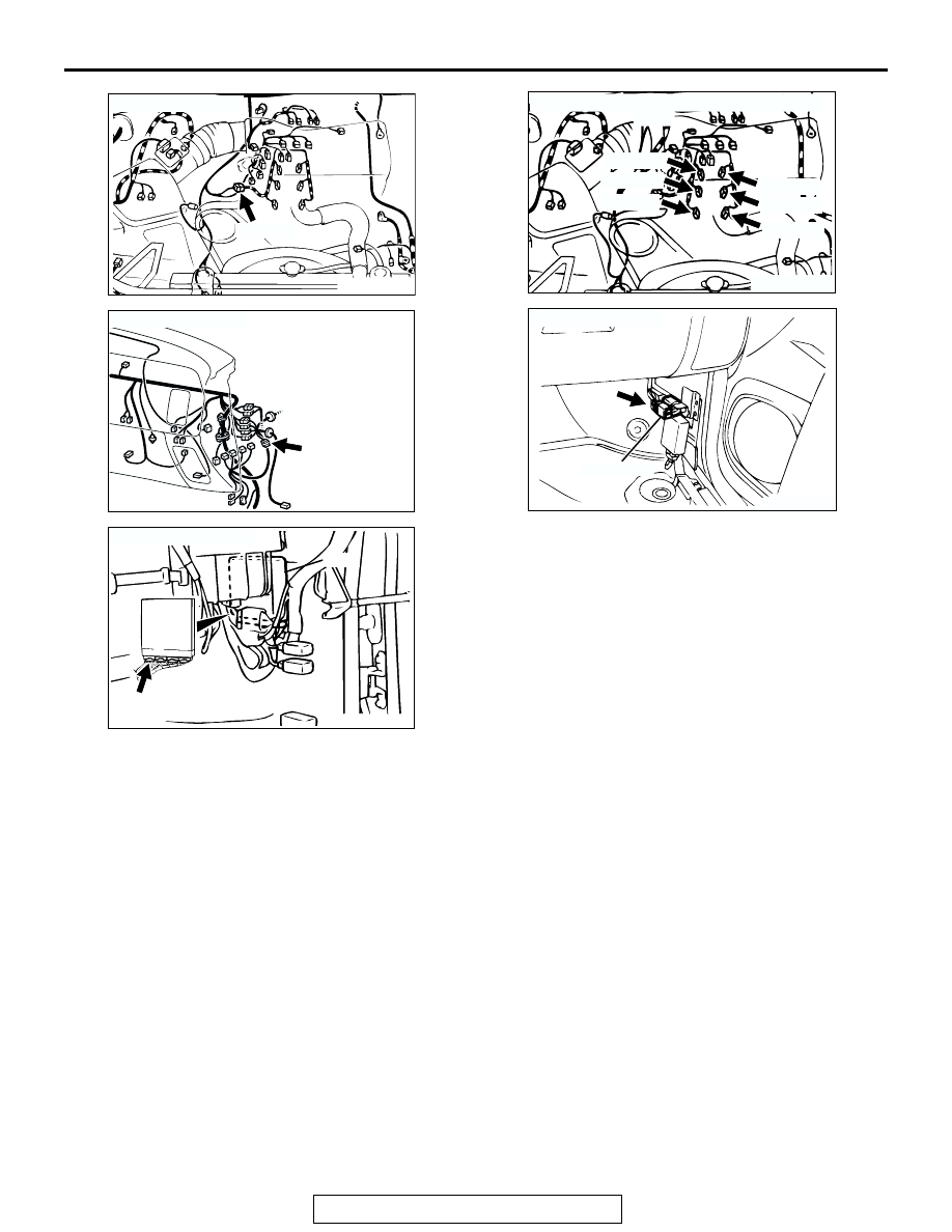
AK200020
CONNECTOR: A-04
AB
A-04(B)
AK103911AB
CONNECTOR: C-14
C-14
AK103738AD
CONNECTOR: C-89
PCM
C-89(GR)
AK200021
AB
A-73(GR)
A-74(GR)
A-75(GR)
A-70(GR)
A-71(GR)
A-72(GR)
CONNECTORS: A-70, A-71, A-72, A-73, A-74,
A-75
AK201000
MFI RELAY
CONNECTOR: C-59
AB
C-59