Mitsubishi Montero Sport (2004+). Manual - part 252
MULTIPORT FUEL INJECTION (MFI) DIAGNOSIS
TSB Revision
MULTIPORT FUEL INJECTION (MFI)
13A-421
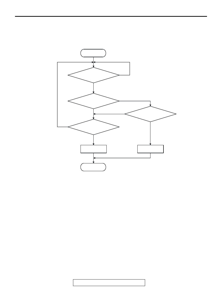
DTC SET CONDITIONS
Logic Flow Chart
.
Check Conditions
• 2 seconds or more have passed since the start-
ing sequence was completed.
Judgement Criteria
• Sensor output voltage has continued to be 4.6
volts or higher for 2 seconds.
.
OBD-II DRIVE CYCLE PATTERN
Refer to Diagnostic Function
− OBD-II Drive Cycle −
Procedure 6
− Other Monitor
.
.
TROUBLESHOOTING HINTS (The most likely
causes for this code to be set are:)
• Fuel tank temperature sensor failed.
• Open fuel tank temperature sensor circuit, har-
ness damage or connector damage.
• PCM failed.
NOTE: A diagnostic trouble code (DTC) could be
output if the engine coolant is changed as indicated
below. Because this is not a failure, the DTC must be
erased.
Make sure to test drive the vehicle in accordance
with the drive cycle pattern in order to verify that a
DTC will not be output.
.
•
The engine and the radiator have been flushed
repeatedly when the engine coolant temperature
was high (or the fuel tank temperature was high).
START
MONITORING
CONDITIONS
END
NO
NO
NO
YES
YES
YES
MALFUNCTION
GOOD
OUTPUT VOLTAGE
< 0.1V
CONTINUOUS
FAILURE FOR 2secs
OUTPUT VOLTAGE
> 4.6V
NO
YES
AK301445