Mitsubishi Montero Sport (2004+). Manual - part 240
MULTIPORT FUEL INJECTION (MFI) DIAGNOSIS
TSB Revision
MULTIPORT FUEL INJECTION (MFI)
13A-373
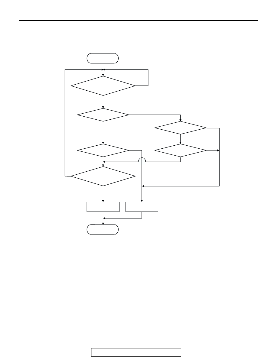
DTC SET CONDITIONS
Logic Flow Chart
.
Check Conditions
• Engine coolant temperature is lower than approx-
imately 100
°C (212°F) when the engine is
started.
• Intake air temperature is lower than 60°C (140°F)
when the engine is started.
• Under the closed loop air/fuel ratio control.
• Engine coolant temperature is higher than 77°C
(171
°F).
• Volume airflow sensor output frequency is 100 Hz
or more.
Judgment Criteria
• Long-term fuel trim has continued to be higher
than +12.5 percent for 5 seconds.
or
• Short-term fuel trim has continued to be higher
than +7.4 percent for 5 seconds.
K
LRN
: LONG-TERM TRIM
K
I
: SHORT-TERM TRIM
K0 : MAXIMUM LIMIT OF LONG-TERM TRIM
K1 : MAXIMUM LIMIT OF SHORT-TERM TRIM
K2 : MINIMUM LIMIT OF LONG-TERM TRIM
K3 : MINIMUM LIMIT OF SHORT-TERM TRIM
START
MONITORING
CONDITIONS
END
NO
NO
NO
NO
NO
NO
YES
YES
YES
YES
YES
YES
K
LRN
> K0
MALFUNCTION
GOOD
K
LRN
< K2
K
I
< K3
K
I
> K1
CONTINUOUS FAILURE
FOR 5secs
AK204050