Mitsubishi Montero Sport (2004+). Manual - part 241
 

  Index      Mitsubishi     Mitsubishi Montero Sport - service repair manual 2004 year


Search            


Content   ..  239  240  241  242   ..


Mitsubishi Montero Sport (2004+). Manual - part 241


MULTIPORT FUEL INJECTION (MFI) DIAGNOSIS

TSB Revision

MULTIPORT FUEL INJECTION (MFI)

13A-377

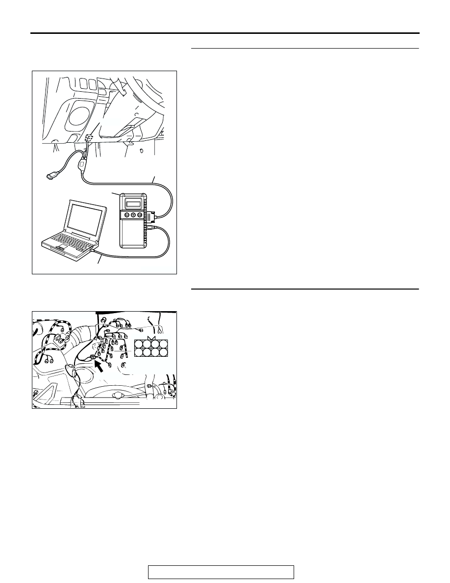
STEP 6. Using scan tool MB991958, check data list item 25: 
Barometric Pressure Sensor.
(1) Turn the ignition switch to the "ON" position.
(2) Set scan tool MB991958 to the data reading mode for item 

25, Barometric Pressure Sensor.

• When altitude is 0 m (0 foot), 101 kPa (29.8 in.Hg) .

• When altitude is 600 m (1,969 feet), 95 kPa (28.1 in.Hg).

• When altitude is 1,200 m (3,937 feet), 88 kPa (26.0 

in.Hg).

• When altitude is 1,800 m (5,906 feet), 81 kPa (23.9 

in.Hg).

(3) Turn the ignition switch to the "LOCK" (OFF) position.
Q: Is the sensor operating properly?

YES : Go to Step 7.
NO :  Refer to, DTC P2227 

− Barometric Pressure Circuit 

Range/Performance Problem

P.13A-684

, DTC P2228 

− Barometric Pressure Temperature Circuit Low Input 

P.13A-692

, DTC P2229 

− Barometric Pressure 

Temperature Circuit High Input 

P.13A-707

.

STEP 7. Check harness connector A-04 at injector 
intermediate connector for damage.
Q: Is the harness connector in good condition?

YES : Go to Step 8.
NO :  Repair or replace it. Refer to GROUP 00E, Harness 

Connector Inspection 

P.00E-2

. Then go to Step 16.

AK303629AB

MB991911

MB991827

MB991824 

16-PIN

AK200014

7

2 1
6 5

4 3
8

CONNECTOR: A-04

AB

FEMALE SIDE 
CONNECTOR

A-04(B)

MULTIPORT FUEL INJECTION (MFI) DIAGNOSIS

TSB Revision

MULTIPORT FUEL INJECTION (MFI)

13A-378

STEP 8. Check the right bank injector resistance at 
intermediate connector A-04.
(1) Disconnect the injector intermediate connector A-04.

(2) Measure the resistance between each injector side 

connector terminal.

a. Measure the resistance between terminal No. 8 and No. 

3 when measuring No. 1 cylinder injector.

b. Measure the resistance between terminal No. 8 and No. 

1 when measuring No. 3 cylinder injector.

c. Measure the resistance between terminal No. 8 and No. 

6 when measuring No. 5 cylinder injector.

• Resistance should be between 13 and 16 ohms [at 20°C 

(68

°F)].

Q: Is the resistance normal?

YES : Go to Step 11.
NO :  Go to Step 9.

STEP 9. Check harness connector A-73, A-74, A-75 at right 
bank injector for damage.
(1) Check the injector connector, which deviates from the 

standard value at Step 8.

Q:  Is the harness connector in good condition?

YES : Go to Step 10.
NO :  Repair or replace it. Refer to GROUP 00E, Harness 

Connector Inspection 

P.00E-2

. Then go to Step 16.

AK200014

7

2 1
6 5

4 3
8

CONNECTOR: A-04

AB

FEMALE SIDE 
CONNECTOR

A-04(B)

AK000452

6

3 4
7 8

1 2
5

INJECTOR
INTERMEDIATE
CONNECTOR

AB

AK200015

1

2

AB

CONNECTORS: A-73, A-74, A-75

A-73(GR)

A-74(GR)

A-75(GR)

HARNESS CONNECTOR: 
COMPONENT SIDE

MULTIPORT FUEL INJECTION (MFI) DIAGNOSIS

TSB Revision

MULTIPORT FUEL INJECTION (MFI)

13A-379

STEP 10. Check the right bank injector.
(1) Remove the intake manifold.
(2) Disconnect the right bank injector connector, which 

deviates from the standard value at Step 8.

(3) Measure the resistance between injector side connector 

terminal No. 1 and No. 2.

Standard value: 13 

 16 ohms [at 20°C (68°F)]

Q: Is the resistance between 13 and 16 ohms?

YES : Repair harness wire between injector intermediate 

connector and right bank injector connector because 
of harness damage. Then go to Step 16.

NO :  Replace the injector. Then go to Step 16.

STEP 11. Check harness connector C-89 at PCM for 
damage.
Q: Is the harness connector in good condition?

YES : Go to Step 12.
NO :  Repair or replace it. Refer to GROUP 00E, Harness 

Connector Inspection 

P.00E-2

. Then go to Step 16.

AK200015

1

2

AB

CONNECTORS: A-73, A-74, A-75

A-73(GR)

A-74(GR)

A-75(GR)

HARNESS CONNECTOR: 
COMPONENT SIDE

AKX01414AB

INJECTOR SIDE
CONNECTOR

1 2

AK103914

2

3

4

5

6

7

8

9

11

12

13

14

15

16

17

18

19

20

30

21

22

23

24

25

26

27

28

29

31

32

33

34

35

1

10

AB

CONNECTOR: C-89

C-89(GR)

HARNESS CONNECTOR:
COMPONENT SIDE

MULTIPORT FUEL INJECTION (MFI) DIAGNOSIS

TSB Revision

MULTIPORT FUEL INJECTION (MFI)

13A-380

STEP 12. Check for harness damage between right bank 
injector connector and PCM connector.

a. Check the harness wire between injector connector A-75 

(terminal No. 2) and PCM connector C-89 (terminal No. 1) 
when checking No.1 cylinder injector.

b. Check the harness wire between injector connector A-74 

(terminal No. 2) and PCM connector C-89 (terminal No. 24) 
when checking No.3 cylinder injector.

c. Check the harness wire between injector connector A-73 

(terminal No. 2) and PCM connector C-89 (terminal No. 10) 
when checking No.5 cylinder injector.

Q: Is the harness wire in good condition?

YES : Go to Step 13.
NO :  Repair it. Then go to Step 16.

STEP 13. Check the fuel pressure.
Refer to On-vehicle Service 

− Fuel Pressure Test 

P.13A-884

.

Q: Are there any abnormalities?

YES : Go to Step 14.
NO :  Repair or replace it. Then go to Step 16.

STEP 14. Check for entry of foreign matter (water, 
kerosene, etc.) into fuel.
Q: Are there any abnormalities?

YES : Go to Step 15.
NO :  Replace the fuel. Then go to Step 16.

AK200015

1

2

AB

CONNECTORS: A-73, A-74, A-75

A-73(GR)

A-74(GR)

A-75(GR)

HARNESS CONNECTOR: 
COMPONENT SIDE

AK103914

2

3

4

5

6

7

8

9

11

12

13

14

15

16

17

18

19

20

30

21

22

23

24

25

26

27

28

29

31

32

33

34

35

1

10

AB

CONNECTOR: C-89

C-89(GR)

HARNESS CONNECTOR:
COMPONENT SIDE


Content   ..  239  240  241  242   ..