Mitsubishi Montero Sport (2004+). Manual - part 238


  Index      Mitsubishi     Mitsubishi Montero Sport - service repair manual 2004 year


Search            


Content   ..  236  237  238  239   ..


Mitsubishi Montero Sport (2004+). Manual - part 238


MULTIPORT FUEL INJECTION (MFI) DIAGNOSIS

TSB Revision

MULTIPORT FUEL INJECTION (MFI)

13A-365

OBD-II DRIVE CYCLE PATTERN
Refer to Diagnostic Function 

− OBD-II Drive Cycle − 

Procedure 6 

− Other Monitor 

P.13A-4

.

.

TROUBLESHOOTING HINTS (The most likely 
causes for this code to be set are:)

• Open or shorted left bank heated oxygen sensor 

(rear) heater circuit, or harness damage.

• Open circuit in left bank heated oxygen sensor 

(rear) heater.

• Left bank heated oxygen sensor (rear) failed.

• Connector damage.

• PCM failed.

DIAGNOSIS

Required Special Tool:

• MD998464: Test Harness Set

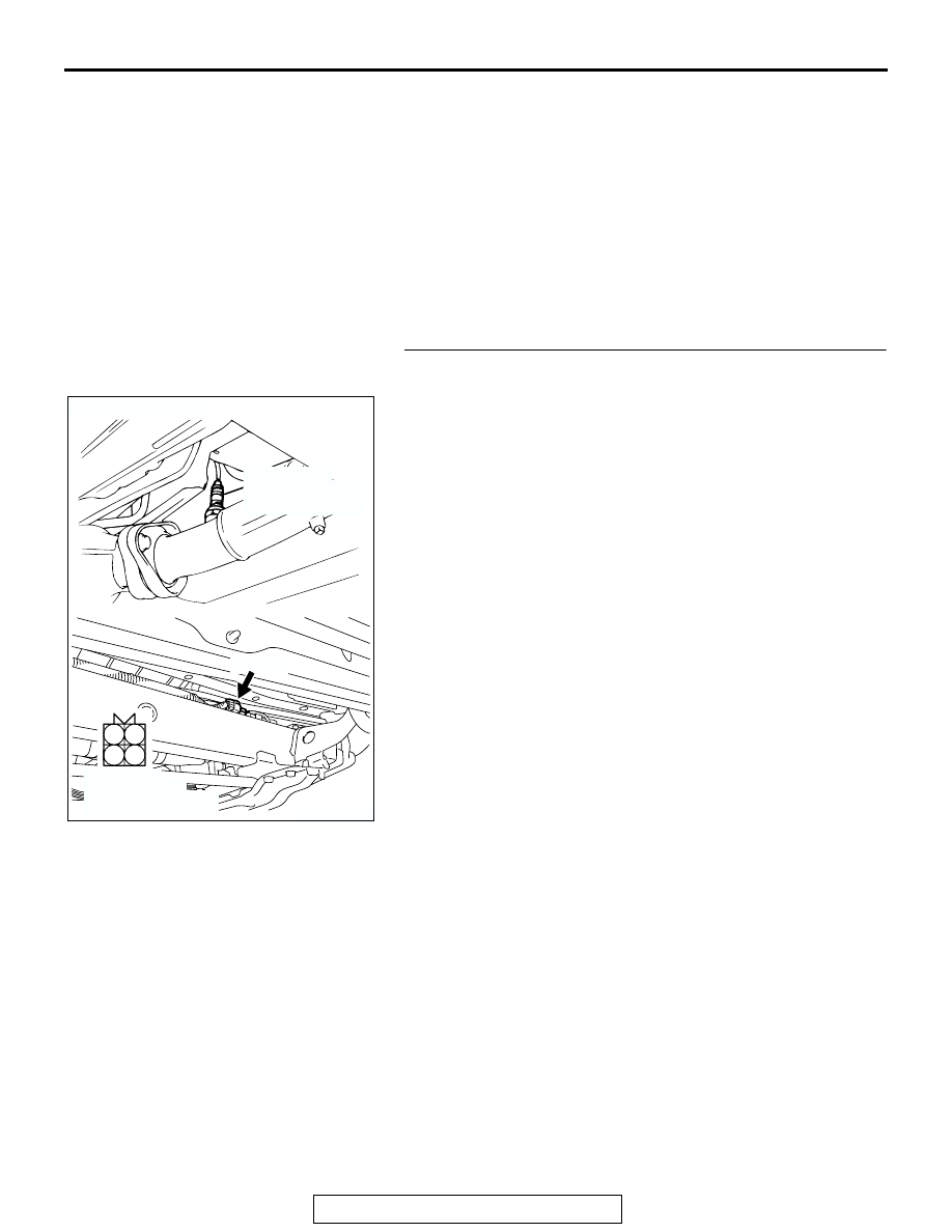
STEP 1. Check connector E-48 at the left bank heated 
oxygen sensor (rear) for damage.
Q: Is the connector in good condition?

YES : Go to Step 2.
NO :  Repair or replace it. Refer to GROUP 00E, Harness 

Connector Inspection 

P.00E-2

. Then go to Step 12.

AK200498

1

2

3

4

E-48(B)

AB

CONNECTOR: E-48

HARNESS 
CONNECTOR: 
COMPONENT SIDE

LEFT BANK
HEATED OXYGEN
SENSOR (REAR)

MULTIPORT FUEL INJECTION (MFI) DIAGNOSIS

TSB Revision

MULTIPORT FUEL INJECTION (MFI)

13A-366

STEP 2. Check the left bank heated oxygen sensor (rear).

(1) Disconnect left bank heated oxygen sensor (rear) connector 

E-48 and connect test harness special tool, MD998464, to 
the connector on the left bank heated oxygen (rear) sensor 
side.

(2) Measure the resistance between heated oxygen sensor 

connector terminal No. 1 (red clip) and terminal No. 3 (blue 
clip).

Standard value: 11 

 18 ohms [at 20°C (68°F)]

Q: Is the measured resistance between 11 and 18 ohms [at 

20

°C (68°F)]?

YES : Go to Step 3.
NO :  Replace the left bank heated oxygen sensor (rear). 

Then go to Step 12.

AK200498

1

2

3

4

E-48(B)

AB

CONNECTOR: E-48

HARNESS 
CONNECTOR: 
COMPONENT SIDE

LEFT BANK
HEATED OXYGEN
SENSOR (REAR)

AKX01624

HEATED
OXYGEN
SENSOR
EQUIPMENT
SIDE
CONNECTOR

MD998464

BLUE

RED

AC

MULTIPORT FUEL INJECTION (MFI) DIAGNOSIS

TSB Revision

MULTIPORT FUEL INJECTION (MFI)

13A-367

STEP 3. Measure the power supply voltage at left bank 
heated oxygen sensor (rear) harness side connector E-48.
(1) Disconnect the connector E-48 and measure at the harness 

side.

(2) Turn the ignition switch to the "ON" position.

(3) Measure the voltage between terminal No. 1 and ground.

• Voltage should be battery positive voltage.

(4) Turn the ignition switch to the "LOCK" (OFF) position.
Q: Is battery positive voltage (approximately 12 volts) 

present?
YES : 
Go to Step 5.
NO :  Go to Step 4.

STEP 4. Check connector C-59 at the MFI relay for damage.
Q: Is the connector in good condition?

YES : Check connector C-14, C-79 and E-45 at 

intermediate connector for damage, and repair or 
replace as required. Refer to GROUP 00E, Harness 
Connector Inspection 

P.00E-2

. If intermediate 

connector is in good condition, repair harness wire 
between MFI relay connector C-59 (terminal No. 1) 
and left bank heated oxygen sensor (rear) connector 
E-48 (terminal No.1) because of open circuit or short 
circuit to ground. Then go to Step 12.

NO :  Repair or replace it. Refer to GROUP 00E, Harness 

Connector Inspection 

P.00E-2

. Then go to Step 12.

AK200498

1

2

3

4

E-48(B)

AB

CONNECTOR: E-48

HARNESS 
CONNECTOR: 
COMPONENT SIDE

LEFT BANK
HEATED OXYGEN
SENSOR (REAR)

AKX01498 BD

2

1

4

3

E-48 HARNESS 
CONNECTOR: 
COMPONENT SIDE

AK200023

2 1

3

4

CONNECTOR: C-59

AB

C-59

HARNESS 
CONNECTOR:
COMPONENT 
SIDE

MULTIPORT FUEL INJECTION (MFI) DIAGNOSIS

TSB Revision

MULTIPORT FUEL INJECTION (MFI)

13A-368

STEP 5. Measure the power supply voltage at PCM 
connector C-89 by backprobing.
(1) Do not disconnect the connector 89.
(2) Turn the ignition switch to the "ON" position.

(3) Measure the voltage between terminal No. 26 and ground 

by backprobing.

• Voltage should be battery positive voltage.

(4) Turn the ignition switch to the "LOCK" (OFF) position.
Q: Is battery positive voltage (approximately 12 volts) 

present?
YES : 
Go to Step 8.
NO :  Go to Step 6.

STEP 6. Check connector C-89 at PCM for damage.
Q: Is the connector in good condition?

YES : Go to Step 7.
NO :  Repair or replace it. Refer to GROUP 00E, Harness 

Connector Inspection 

P.00E-2

. Then go to Step 12.

AK103914

2

3

4

5

6

7

8

9

11

12

13

14

15

16

17

18

19

20

30

21

22

23

24

25

26

27

28

29

31

32

33

34

35

1

10

AB

CONNECTOR: C-89

C-89(GR)

HARNESS CONNECTOR:
COMPONENT SIDE

AKX01543

AKX01543

1

2

3 4

5 6

7 8

10 11 12 13 14 15 16 17 18 19 20 21 22 23

24 25

26 27 28 29

30 31 32 33

34 35

C-89 HARNESS CONNECTOR: 
HARNESS SIDE

AH

9

AK103914

2

3

4

5

6

7

8

9

11

12

13

14

15

16

17

18

19

20

30

21

22

23

24

25

26

27

28

29

31

32

33

34

35

1

10

AB

CONNECTOR: C-89

C-89(GR)

HARNESS CONNECTOR:
COMPONENT SIDE


Content   ..  236  237  238  239   ..