Mitsubishi Montero Sport (2004+). Manual - part 176


  Index      Mitsubishi     Mitsubishi Montero Sport - service repair manual 2004 year


Search            


Content   ..  174  175  176  177   ..


Mitsubishi Montero Sport (2004+). Manual - part 176


MULTIPORT FUEL INJECTION (MFI) DIAGNOSIS

TSB Revision

MULTIPORT FUEL INJECTION (MFI)

13A-117

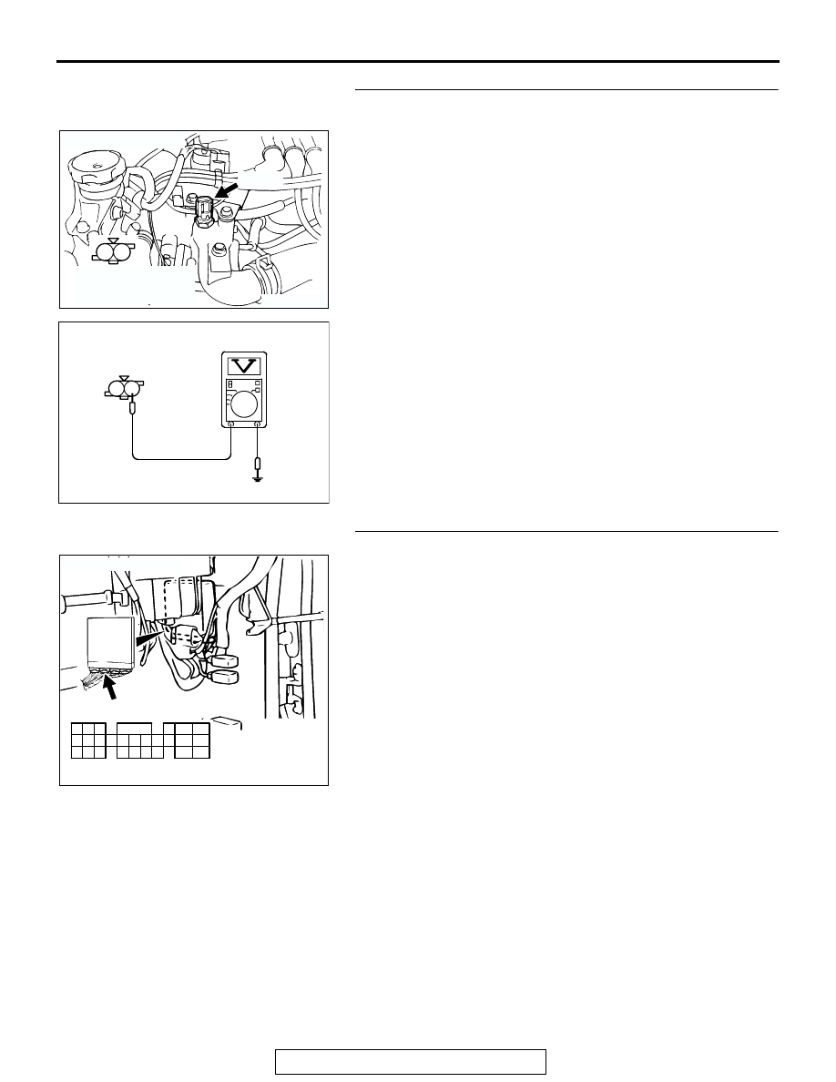
STEP 6. Measure the sensor supply voltage at engine 
coolant temperature sensor harness side connector A-67.
(1) Disconnect the connector A-67 and measure at the harness 

side.

(2) Turn the ignition switch to the "ON" position.

(3) Measure the voltage between terminal No. 1 and ground.

• Voltage should be between 4.5 and 4.9 volts.

(4) Turn the ignition switch to the "LOCK" (OFF) position.
Q: Is the measured voltage between 4.5 and 4.9 volts?

YES : Go to Step 8.
NO :  Go to Step 7.

STEP 7. Check connector C-90 at PCM for damage.
Q: Is the connector in good condition?

YES : Replace the PCM. Then go to Step 14.
NO :  Repair or replace it. Refer to GROUP 00E, Harness 

Connector Inspection 

P.00E-2

. Then go to Step 14.

AK104023

1

2

A-67(B)

AB

CONNECTOR: A-67

HARNESS 
CONNECTOR: 
COMPONENT SIDE

AK000234

A-67 HARNESS 
CONNECTOR: 
COMPONENT SIDE

2 1

AO

AK103762

42

43

48

49

50

51

52

53

54

55

56

57

46 45 44

58

59

60

61

62

63

64

65

66

47

41

AB

CONNECTOR: C-90

C-90(GR)

HARNESS CONNECTOR:
COMPONENT SIDE

MULTIPORT FUEL INJECTION (MFI) DIAGNOSIS

TSB Revision

MULTIPORT FUEL INJECTION (MFI)

13A-118

STEP 8. Check for continuity at engine coolant 
temperature sensor harness side connector A-67.
(1) Disconnect the connector A-67 and measure at the harness 

side.

(2) Check for the continuity between terminal No. 2 and 

ground.

• Should be less than 2 ohms.

Q: Does continuity exist?

YES : Go to Step 11.
NO :  Go to Step 9.

STEP 9. Check connector C-90 at PCM for damage.
Q: Is the connector in good condition?

YES : Go to Step 10.
NO :  Repair or replace it. Refer to GROUP 00E, Harness 

Connector Inspection 

P.00E-2

. Then go to Step 14.

AK104023

1

2

A-67(B)

AB

CONNECTOR: A-67

HARNESS 
CONNECTOR: 
COMPONENT SIDE

AK000235

A-67 HARNESS 
CONNECTOR: 
COMPONENT SIDE

2 1

AK

AK103762

42

43

48

49

50

51

52

53

54

55

56

57

46 45 44

58

59

60

61

62

63

64

65

66

47

41

AB

CONNECTOR: C-90

C-90(GR)

HARNESS CONNECTOR:
COMPONENT SIDE

MULTIPORT FUEL INJECTION (MFI) DIAGNOSIS

TSB Revision

MULTIPORT FUEL INJECTION (MFI)

13A-119

STEP 10. Check for harness damage between engine 
coolant temperature sensor connector A-67 (terminal No. 
2) and PCM connector C-90 (terminal No. 57).

NOTE: Check harness after checking intermediate connector 
C-71. If intermediate connector is damaged, repair or replace it. 
Refer to GROUP 00E, Harness Connector Inspection

P.00E-2

Then go to Step 14.
Q: Is the harness wire in good condition?

YES : Replace the PCM. Then go to Step 14. 
NO :  Repair it. Then go to Step 14. 

AK104023

1

2

A-67(B)

AB

CONNECTOR: A-67

HARNESS 
CONNECTOR: 
COMPONENT SIDE

AK103762

42

43

48

49

50

51

52

53

54

55

56

57

46 45 44

58

59

60

61

62

63

64

65

66

47

41

AB

CONNECTOR: C-90

C-90(GR)

HARNESS CONNECTOR:
COMPONENT SIDE

MULTIPORT FUEL INJECTION (MFI) DIAGNOSIS

TSB Revision

MULTIPORT FUEL INJECTION (MFI)

13A-120

STEP 11. Check the engine coolant temperature sensor.
(1) Disconnect the engine coolant temperature sensor 

connector A-67.

(2) Remove the engine coolant temperature sensor.

(3) With the temperature sensing portion of engine coolant 

temperature sensor immersed in hot water, check 
resistance.

Standard value:

14 

 17 k [at 20°C (4°F)]

5.1 

 6.5 k [at 0°C (32°F)]

2.1 

 2.7 k [at 20°C (68°F)]

0.9 

 1.3 k [at 40°C (104°F)]

0.48 

 0.68 k [at 60°C (140°F)]

0.26 

 0.36 k [at 80°C (176°F)]

(4) Apply 3M

 AAD part number 8731 or equivalent on the 

screw section of the engine coolant temperature sensor.

(5) Install the engine coolant temperature sensor, and tighten 

to the specified torque.

Tightening torque: 29 

± 10 Nm (22 ± 7 ft-lb)

Q: Is the resistance at the standard value?

YES : Go to Step 12.
NO :  Replace the engine coolant temperature sensor. Then 

go to Step 14.

STEP 12. Check connector C-90 at PCM for damage.
Q: Is the connector in good condition?

YES : Go to Step 13.
NO :  Repair or replace it. Refer to GROUP 00E, Harness 

Connector Inspection 

P.00E-2

. Then go to Step 14.

AK104023

1

2

A-67(B)

AB

CONNECTOR: A-67

HARNESS 
CONNECTOR: 
COMPONENT SIDE

AKX01622

AKX01623 AB

AK103762

42

43

48

49

50

51

52

53

54

55

56

57

46 45 44

58

59

60

61

62

63

64

65

66

47

41

AB

CONNECTOR: C-90

C-90(GR)

HARNESS CONNECTOR:
COMPONENT SIDE


Content   ..  174  175  176  177   ..