Mitsubishi Montero Sport (2004+). Manual - part 123


  Index      Mitsubishi     Mitsubishi Montero Sport - service repair manual 2004 year


Search            


Content   ..  121  122  123  124   ..


Mitsubishi Montero Sport (2004+). Manual - part 123


AUTO-CRUISE CONTROL

TSB Revision

ENGINE AND EMISSION CONTROL

17-87

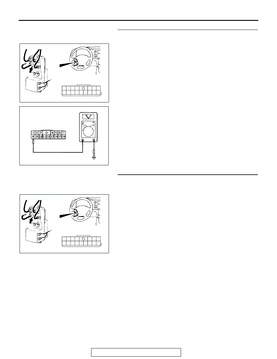
STEP 3. Measure the output circuit voltage at junction 
block connector D-06 by backprobing.
(1) Do not disconnect junction block connector D-06.
(2) Turn the ignition switch to the "ON" position.

(3) Measure the voltage between junction block connector 

D-06 terminal 8 and ground by backprobing.

(4) Turn the ignition switch to the "LOCK" (OFF) position.
Q: Is measure voltage approximately battery positive 

voltage?
YES : 
Go to Step 5 .
NO :  Go to Step 4 .

STEP 4. Check junction block connector D-06 for loose, 
corroded or damaged terminals, or terminals pushed back 
in the connector.
Q: Is the connector damaged?

YES : Repair or replace the damaged connector. (Refer to 

GROUP 00E, Harness Connector Inspection   

P.00E-2

). Then go to Step 11 

NO :  Replace the junction block. Then go to Step 11 .

AC203161

1
8

3

4

5

7 6

10

15

16

14

12

13

11

9

2

D-06

AB

D-06: HARNESS 
SIDE CONNECTOR

CONNECTOR: D-06

JUNCTION BLOCK
 (FRONT)

AC103742AC

D-06 HARNESS CONNECTOR:
HARNESS SIDE

AC203161

1
8

3

4

5

7 6

10

15

16

14

12

13

11

9

2

D-06

AB

D-06: HARNESS 
SIDE CONNECTOR

CONNECTOR: D-06

JUNCTION BLOCK
 (FRONT)

AUTO-CRUISE CONTROL

TSB Revision

ENGINE AND EMISSION CONTROL

17-88

STEP 5. Check combination meter connector C-04 and 
C-05 for loose, corroded or damaged terminals, or 
terminals pushed back in the connector.
Q: Is any connector damaged?

YES : Repair or replace the damaged connector. (Refer to 

GROUP 00E, Harness Connector Inspection 

P.00E-2

). Then go to Step 11 .

NO :  Go to Step 6 .

STEP 6. Check the harness wire between combination 
meter connector C-04 (terminal No.24) and junction block 
connector D-06 (terminal No.8).
Q: Is any harness wire between combination meter 

connector C-04 (terminal No.24)and junction block 
connector D-06 (terminal No.8)damaged?
YES : 
Repair the harness wire. Then go to Step 11 .
NO :  Go to Step 7 .

AC202163

21

23

24

27 26 25

22

28

30

31

29

32

3 2

6 5 4

7

8

9

11 10

1

12

14 13

CONNECTORS: C-04, C-05

AB

C-04 C-05

C-04 HARNESS SIDE

C-05 HARNESS SIDE

AC201897

21

23

24

27 26 25

22

28

30

31

29

32

CONNECTOR: C-04

AB

C-04: HARNESS SIDE 
CONNECTOR

C-04

AC203161

1
8

3

4

5

7 6

10

15

16

14

12

13

11

9

2

D-06

AB

D-06: HARNESS 
SIDE CONNECTOR

CONNECTOR: D-06

JUNCTION BLOCK
 (FRONT)

AUTO-CRUISE CONTROL

TSB Revision

ENGINE AND EMISSION CONTROL

17-89

STEP 7. Check the combination meter.
(1) Remove the combination meter (Refer to GROUP 54, 

Combination Meter Assembly 

P.54-119

).

(2) Measure at the combination meter side connector C-04 and 

C-05.

(3) Measure the continuity between combination meter 

connector C-04 terminal 24 and combination meter 
connector C-05 terminal 8.

Q: Is the measured continuity less than 2 ohms?

YES : Go to Step 8 
NO :  Replace the combination meter. (Refer to GROUP 54, 

Combination Meter Assembly 

P.54-119

). Then go to 

Step 11 .

STEP 8. Check auto-cruise control-ECU connector C-35 for 
loose, corroded or damaged terminals, or terminals 
pushed back in the connector.
Q: Is the connector damaged?

YES : Repair or replace the damaged connector. (Refer to 

GROUP 00E, Harness Connector Inspection 

P.00E-2

). Then go to Step 11 .

NO :  Go to Step 9 .

AC004775

CONNECTORS: C-04, C-05

AB

C-04

C-05

AC004780 AD

C-04 
HARNESS CONNECTOR:
COMBINATION METER SIDE 

C-05 
HARNESS CONNECTOR:
COMBINATION METER SIDE 

AC202155

2

3

10

11

5

6

13

14

12

4

8

16 15

7

9

1

C-35 (B)

AB

CONNECTOR: C-35

C-35 HARNESS SIDE 
CONNECTOR

AUTO-CRUISE CONTROL

TSB Revision

ENGINE AND EMISSION CONTROL

17-90

STEP 9. Check the harness wire between combination 
meter connector C-05 (terminal No.8) and auto-cruise 
control-ECU connector C-35 (terminal No.15).
Q: Is any harness wire between combination meter 

connector C-05 (terminal No.8) and auto-cruise 
control-ECU connector C-35 (terminal No.15)damaged?
YES : 
Repair or replace the harness wire. Then go to Step 

11.

NO :  Go to Step 10 .

STEP 10. Check that the malfunction is eliminated
Q: Is the malfunction eliminated?

YES : It can be assumed that this malfunction is intermittent. 

(Refer to GROUP 00, How to Use 
Troubleshooting/Inspection Service Points 

− How to 

Cope with Intermittent Malfunction 

P.00-7

).

NO :  Replace the auto-cruise control-ECU. (Refer to 

P.17-99

). Then go to Step 11 .

STEP 11. Check that the malfunction is eliminated
Q: Is the malfunction eliminated?

YES : This procedure is complete.
NO :  Return to Step 1 .

AC2018743

3 2

6 5 4

7

8

9

1110

1

12

1413

CONNECTOR: C-05

C-05 HARNESS CONNECTOR

C-05

AC201843 AB

AC202155

2

3

10

11

5

6

13

14

12

4

8

16 15

7

9

1

C-35 (B)

AB

CONNECTOR: C-35

C-35 HARNESS SIDE 
CONNECTOR


Content   ..  121  122  123  124   ..