Mitsubishi Montero Sport (2004+). Manual - part 124


  Index      Mitsubishi     Mitsubishi Montero Sport - service repair manual 2004 year


Search            


Content   ..  122  123  124  125   ..


Mitsubishi Montero Sport (2004+). Manual - part 124


AUTO-CRUISE CONTROL

TSB Revision

ENGINE AND EMISSION CONTROL

17-91

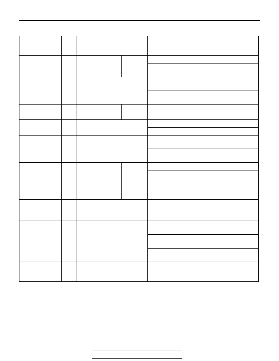
DATA LIST REFERENCE TABLE

M1172002400363

SCAN TOOL 
MB991958 
DISPLAY

ITEM 
NO.

INSPECTION ITEM

INSPECTION 
REQUIREMENT

NORMAL CONDITION

CANCEL 
SWITCH

04

Auto-cruise control 
switch

CANCEL

CANCEL switch: "ON" ON
CANCEL switch: 
"OFF"

OFF

IDLE SW SIG

08

Idle position signal

Accelerator pedal: 
Depressed

OFF

Accelerator pedal: 
Released

ON

MAIN SW

01

Auto-cruise control 
switch

MAIN

MAIN switch: "ON"

ON

MAIN switch: "OFF"

OFF

OD OFF

15

A/T control signal

Driving on level road

OFF

Driving on uphill grade ON

PNP 
SW/CLUTCH

14

Park/neutral position switch

Selector lever: "P" or 
"N" position 

ON

Selector lever: Other 
than "P" or "N" position 

OFF

RESUME 
SWITCH

03

Auto-cruise control 
switch

RESUME RESUME switch: "ON" ON

RESUME switch: 
"OFF"

OFF

SET SWITCH

02

Auto-cruise control 
switch

SET

SET switch: "ON"

ON

SET switch: "OFF"

OFF

STOPLIGHT SW 05

Stoplight switch

Brake pedal: 
Depressed

ON

Brake pedal: Released OFF

TP SENSOR

13

Throttle position sensor

Accelerator pedal: 
Released

535 

− 735 mV

Accelerator pedal: 
Depressed

Increases in proportion 
to throttle opening angle

Accelerator pedal: 
Fully depressed

4,500 

− 5,500 mV

VSS

10

Vehicle speed sensor

Road test the vehicle

The speedometer and 
scan tool MB991958 
display the same value.

AUTO-CRUISE CONTROL

TSB Revision

ENGINE AND EMISSION CONTROL

17-92

CHECK AUTO-CRUISE CONTROL-ECU TERMINALS

M1172002700320

ACX02234

TERMINAL 
NO.

INSPECTION 
ITEM

INSPECTION CONDITION

NORMAL 
CONDITION

1

Throttle 
position 
sensor input

When accelerator pedal is fully depressed

4.5 

− 5.5 V

When accelerator pedal is released

0.535 

− 0.735 V

2

Idle position 
signal

When accelerator pedal is depressed

4 V or more

When accelerator pedal is not depressed

− 1 V

3

A/T control 
output

Driving on level load

Battery positive 
voltage

Driving on uphill grade

0 V

4

Stoplight 
switch input

When brake pedal is depressed When stoplight 

switch is ON

Battery positive 
voltage

When brake pedal is not 
depressed

When stoplight 
switch is OFF

0 V

5

Pump power 
supply

Ignition switch: ON Main switch: ON
Stoplight switch: ON (When brake pedal is not 
depressed)

Battery positive 
voltage

6

ECU power 
supply

Ignition switch: ON

Battery positive 
voltage

7

Release valve When decelerating with the "SET" switch while driving 

at constant speed

Battery positive 
voltage

8

Control valve

Battery positive 
voltage

7

Release valve When cancelling constant speed driving with the 

"CANCEL" switch

Battery positive 
voltage

8

Control valve

Battery positive 
voltage

9

Auto-cruise 
control switch 
output

At any time

0 V

10

Vehicle speed 
sensor input

When vehicle is moved forwards 
and backwards, sensor turns 
ON and OFF repeatedly

When sensor is ON

0 V

When sensor is OFF 8 - 12 V*

AUTO-CRUISE CONTROL

TSB Revision

ENGINE AND EMISSION CONTROL

17-93

NOTE: *: The No. 10 terminal of the auto-cruise con-
trol-ECU outputs a voltage of 5 V, but actually indi-
cates 8 to 12 V, because a voltage circulates through 
the speedometer circuit.

12

ACC power 
supply

When main switch is ON

Approximately 9.0 V

When input switch has not been 
operated

When all switches 
are OFF

Approximately 4.5 V

When input switch is pushed 
down

When "SET" switch 
is ON

Approximately 1.5 V

When input switch is pushed up When "RESUME" 

switch is ON

Approximately 3.0 V

When input switch is pulled 
forward

When "CANCEL" 
switch is ON

Approximately 0 V

13

Park/neutral 
position switch 
input 

When select lever is in a position 
other than "N" or "P" range

When park/neutral 
position switch is 
OFF

Battery positive 
voltage

When select lever is in "N" or "P" 
range

When park/neutral 
position switch is ON

0 V

14

Ground

At any time

0 V

15

Indicator light 
input (inside 
combination 
meter)

When main switch is ON

When indicator light 
is illuminated

0 V

When main switch is OFF

When indicator light 
is switch off

Battery positive 
voltage

16

Auto-cruise 
vacuum pump 
motor input

When driving with the constant 
speed control

Motor 
stopped/running

Battery positive 
voltage/0 V

When accelerating with the 
"ACCELERATOR" switch while 
driving at constant speed

Motor 
stopped/running

Battery positive 
voltage/0 V

When decelerating with the 
"COAST" switch while driving at 
constant speed

Motor stopped

Battery positive 
voltage

When cancelling constant speed 
driving with the "CANCEL" 
switch

Motor stopped

Battery positive 
voltage

TERMINAL 
NO.

INSPECTION 
ITEM

INSPECTION CONDITION

NORMAL 
CONDITION

AUTO-CRUISE CONTROL

TSB Revision

ENGINE AND EMISSION CONTROL

17-94

SPECIAL TOOLS

M1172000600349

TOOL

TOOL NUMBER AND 
NAME

SUPERSESSION

APPLICATION

MB991958
F: MB991825

A: MB991824
B: MB991827
C: MB991910
D: MB991911
E: MB991914
G: MB991826

MUT-III sub assembly

A: Vehicle 

communication 
interface (V.C.I.)

B: MUT-III USB cable
C: MUT-III main harness 

A (Vehicles with CAN 
communication 
system)

D: MUT-III main harness 

B (Vehicles without 
CAN communication 
system)

E: MUT-III main harness 

C (for Daimler Chrysler 
models only)

F: MUT-III measurement
G: MUT-III trigger 

harness

MB991824-KIT
NOTE: G: MB991826 
MUT-III trigger harness is 
not necessary when 
pushing V.C.I ENTER key

Reading diagnostic 
trouble code

MB991910

MB991826

MB991958

MB991911

MB991914

MB991824

MB991827

MB991825

DO NOT USE

A

B

C

D

E

F

G

DO NOT USE


Content   ..  122  123  124  125   ..