Mitsubishi Montero Sport (2004+). Manual - part 121


  Index      Mitsubishi     Mitsubishi Montero Sport - service repair manual 2004 year


Search            


Content   ..  119  120  121  122   ..


Mitsubishi Montero Sport (2004+). Manual - part 121


AUTO-CRUISE CONTROL

TSB Revision

ENGINE AND EMISSION CONTROL

17-79

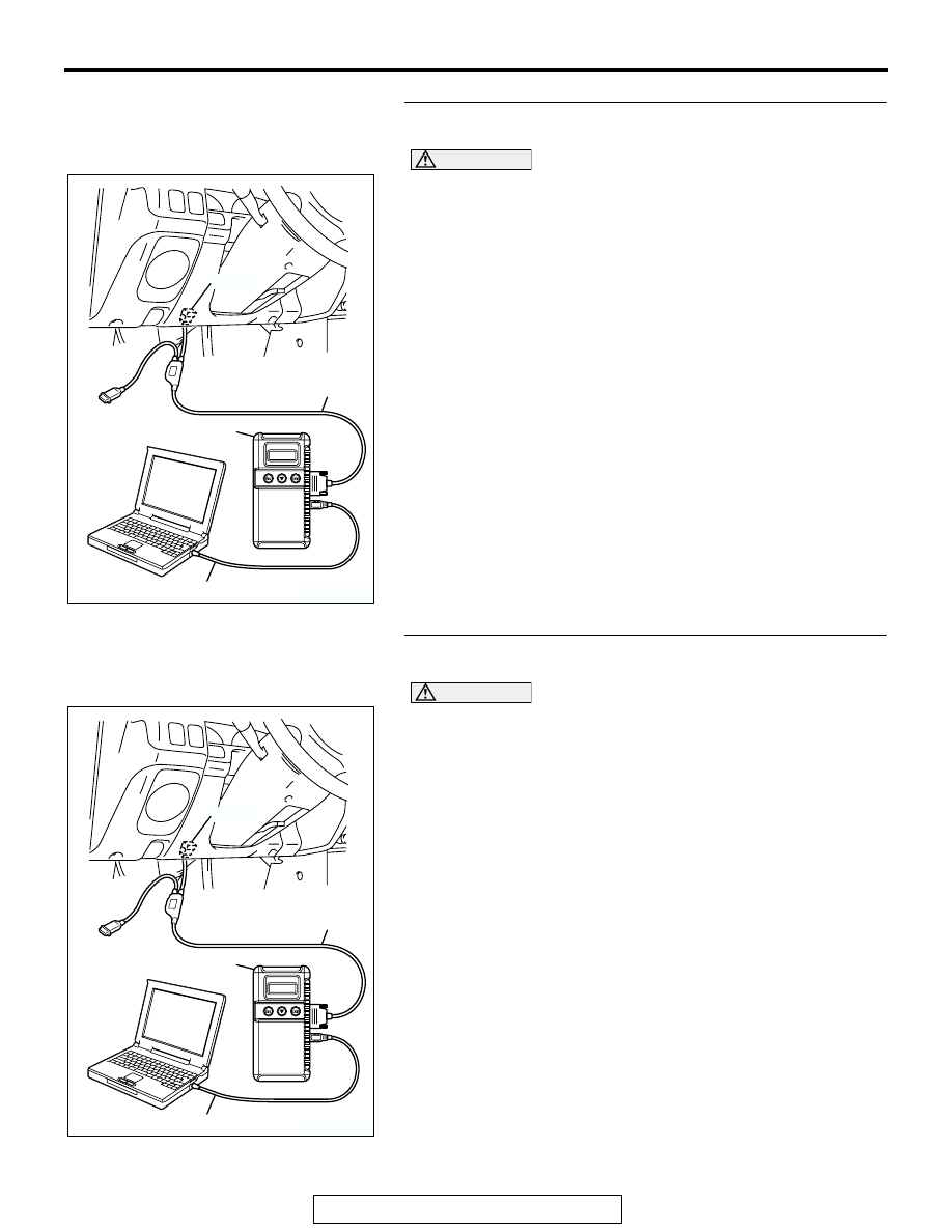
STEP 3. Using scan tool MB991958, check data list item 04: 
auto-cruise control "CANCEL" switch.

CAUTION

To prevent damage to scan tool MB991958, always turn the 
ignition switch to the "LOCK" (OFF) position before con-
necting or disconnecting scan tool MB991958.
(1) Using scan tool MB991958.
(2) Connect scan tool MB991958 to the data link connector.
(3) Set scan tool MB991958 to data reading mode for 

auto-cruise control system item 04, auto-cruise control 
"CANCEL" switch.

• When auto-cruise control "CANCEL" switch is at the ON 

position, the display on scan tool MB991958 should be 
"ON".

• When auto-cruise control "CANCEL" switch is at the 

OFF position, the display on scan tool MB991958 
should be "OFF".

(4) Turn the ignition switch to the "ON" position.
Q: Is the switch operating properly?

YES : Go to Step 4 .
NO :  Go to Diagnostic Trouble Code Procedures number 

15 (Refer to 

P.17-34

).

STEP 4. Using scan tool MB991958, check data list item 05: 
stoplight switch.

CAUTION

To prevent damage to scan tool MB991958, always turn the 
ignition switch to the "LOCK" (OFF) position before con-
necting or disconnecting scan tool MB991958.
(1) Using scan tool MB991958.
(2) Connect scan tool MB991958 to the data link connector.
(3) Set scan tool MB991958 to data reading mode for 

auto-cruise control system item 05, stoplight switch.

• When brake pedal is depressed, the display on scan 

tool MB991958 should be "ON".

• When brake pedal is released, the display on scan tool 

MB991958 should be "OFF".

(4) Turn the ignition switch to the "ON" position.
Q: Is the switch operating properly?

YES : Go to Step 5 .
NO :  Go to Symptom Procedures number 2 (Refer to 

P.17-62

).

AK303629AB

MB991911

MB991827

MB991824 

16-PIN

AK303629AB

MB991911

MB991827

MB991824 

16-PIN

AUTO-CRUISE CONTROL

TSB Revision

ENGINE AND EMISSION CONTROL

17-80

STEP 5. Using scan tool MB991958, check data list item 14: 
park/neutral position switch.

CAUTION

To prevent damage to scan tool MB991958, always turn the 
ignition switch to the "LOCK" (OFF) position before con-
necting or disconnecting scan tool MB991958.
(1) Using scan tool MB991958.
(2) Connect scan tool MB991958 to the data link connector.
(3) Set scan tool MB991958 to data reading mode for 

auto-cruise control system item 14, park/neutral position 
switch.

• When selector lever is at the "P" or "N" position, the dis-

play on scan tool MB991958 should be "ON".

• When selector lever is other than "P" and "N" position, 

the display on scan tool MB991958 should be "OFF".

(4) Turn the ignition switch to the "ON" position.
Q: Is the switch operating properly?

YES : Go to Step 6 .
NO :  Go to Symptom Procedures number 3 (Refer to 

P.17-71

).

STEP 6. Check that the malfunction is eliminated
Q: Is the malfunction eliminated?

YES : It can be assumed that this malfunction is intermittent. 

(Refer to GROUP 00, How to Use 
Troubleshooting/Inspection Service Points 

− How to 

Cope with Intermittent Malfunction 

P.00-7

).

NO :  Replace the auto-cruise control-ECU. (Refer to 

P.17-99

). Then go to Step 7 .

STEP 7. Check that the malfunction is eliminated
Q: Is the malfunction eliminated?

YES : This procedure is complete.
NO :  Return to Step 1 .

AK303629AB

MB991911

MB991827

MB991824 

16-PIN

AUTO-CRUISE CONTROL

TSB Revision

ENGINE AND EMISSION CONTROL

17-81

INSPECTION PROCEDURE 6: Hunting (Repeated Acceleration and Deceleration) Occurs at the Set 
Vehicle Speed.

.

TECHNICAL DESCRIPTION (COMMENT)
The cause is probably the malfunction of the vehicle 
speed sensor or incorrect vacuum in the auto-cruise 
control vacuum pump or actuator.

.

TROUBLESHOOTING HINTS

• Malfunction of the vehicle speed sensor

• Malfunction of the auto-cruise control vacuum 

pump

• Malfunction of the vacuum actuator (accelerator 

lever body assembly)

• Malfunction of the auto-cruise control-ECU

DIAGNOSIS

Required Special Tool:

• MB991223: Harness set

STEP 1. Check the vehicle speed sensor.
(1) Disconnect the vehicle speed sensor connector B-09.

(2) Remove the vehicle speed sensor and connect a 3 

− 10 kΩ 

resistor as shown in the illustration.

(3) Turn the shaft of the vehicle speed sensor and check that 

there is voltage between terminals 2 

− 3 (one turn = four 

pulses).

Q: Is the voltage within specifications?

YES : Go to Step 2 .
NO :  Replace the vehicle speed sensor. Then go to Step 5 .

AC003458 AC

CONNECTOR: B-09 
<RWD>

B-09 (B)

1

2

3

B-09: HARNESS 
SIDE CONNECTOR

AC201841

3 2 1

CONNECTOR: B-09 

AB

B-09: HARNESS 
SIDE CONNECTOR

<4WD>

B-09 (B)

AC004754

TURN

SHAFT

OHMMETER

RESISTOR
3 - 10 k

AB

AUTO-CRUISE CONTROL

TSB Revision

ENGINE AND EMISSION CONTROL

17-82

STEP 2. Check the auto-cruise vacuum pump.
(1) Disconnect the vacuum hose from the auto-cruise vacuum 

pump and connect a vacuum gauge to the vacuum pump.

(2) Disconnect the vacuum pump connector A-02.

(3) Check the auto-cruise vacuum pump and valves according 

to the following procedure:

• Connect the positive battery terminal to auto-cruise vac-

uum pump side connector A-02 terminal 1, and the neg-
ative battery terminal to terminals 2, 3, and 4. Then the 
vacuum gauge should read 27 kPa (8.0 in Hg) or more.

• The vacuum should be maintained when auto-cruise 

vacuum pump side connector A-02 terminal 4 is discon-
nected from the negative battery terminal while termi-
nals 1, 2, and 3 remain connected. Then the vacuum 
gauge should read 0 kPa (0 in Hg) when terminal 2 is 
disconnected from the negative battery terminal while 
terminals 1, and 3 remain connected.

• The vacuum should be maintained when auto-cruise 

vacuum pump side connector A-02 terminal 4 is discon-
nected from the negative battery terminal while termi-
nals 1, 2, and 3 remain connected. Then the vacuum 
gauge should read 0 kPa (0 in Hg) when terminal 3 is 
disconnected from the negative battery terminal while 
terminals 1, and 2 remain connected.

Q: Are all of the above values satisfied?

YES : Go to Step 3 .
NO :  Replace the auto-cruise vacuum pump. (Refer to 

P.17-99

). Then go to Step 5 .

STEP 3. Check the vacuum actuator.
(1) Disconnect the vacuum hose from the vacuum actuator, 

and then connect a hand vacuum pump to the vacuum 
actuator.

(2) Apply a vacuum and check that the throttle lever moves and 

the vacuum is maintained.

Q: Is the vacuum actuator damaged?

YES : Replace the vacuum actuator (accelerator lever body 

assembly). (Refer to GROUP 13A, Throttle Body 
Assembly 

P.13A-903

). Then go to Step 5 .

NO :  Go to Step 4 .

AC004746

CONNECTOR: A-02

HYDRAULIC
UNIT

AD

A-02 (B)

AC004749 AE

VACUUM GAUGE

A-02 
HARNESS CONNECTOR:
AUTO CRUISE VACUUM 
PUMP CONNECTOR SIDE

AC004774 AB

VACUUM
ACTUATOR


Content   ..  119  120  121  122   ..