Mitsubishi Montero (2004+). Manual - part 970


  Index      Mitsubishi     Mitsubishi Montero - service repair manual 2004 year


Search            


Content   ..  968  969  970  971   ..


Mitsubishi Montero (2004+). Manual - part 970


TRANSFER DIAGNOSIS <ACTIVE TRAC AWD II>

TSB Revision

AUTOMATIC TRANSMISSION

23A-455

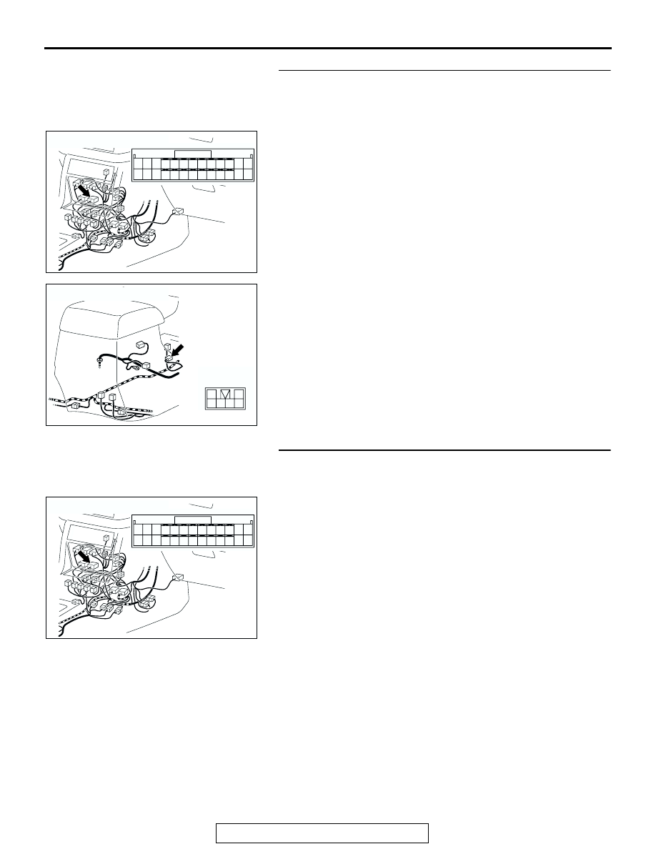
STEP 8. Check harness for open circuit or short circuit to 
ground between transfer-ECU connector E-109 terminal 20 
(21, 22 and 23) and transfer shift lever switch connector 
E-116 terminal 3 (5, 6 and 2).
Q: Is the harness wire in good condition?

YES : Go to Step 10.
NO :  Repair or replace the harness wire.

STEP 9. Check transfer-ECU connector E-109 for loose, 
corroded or damaged terminals, or terminals pushed back 
in the connector.
Q: Are the connector and terminals in good condition?

YES : Go to Step 10.
NO :  Repair or replace the damaged components. Refer to 

GROUP 00E, Harness Connector Inspection 

P.00E-2

.

AC204176

CONNECTOR : E-109

BB

11 12

25

24

13

26

9

22

7

6

20

19

8

21

10

23

5

4

17

2

1

15

14

3

16

18

AC204175

CONNECTOR : E-116

AH

6

2

5

4

3

1

AC204176

CONNECTOR : E-109

BB

11 12

25

24

13

26

9

22

7

6

20

19

8

21

10

23

5

4

17

2

1

15

14

3

16

18

TRANSFER DIAGNOSIS <ACTIVE TRAC AWD II>

TSB Revision

AUTOMATIC TRANSMISSION

23A-456

STEP 10. Using scan tool MB991958, check data list item 
06: Transfer Shift Lever Position.

CAUTION

To prevent damage to scan tool MB991958, always turn the 
ignition switch to the "LOCK" (OFF) position before con-
necting or disconnecting scan tool MB991958.
(1) Connect scan tool MB991958 to the data link connector.
(2) Turn the ignition switch to the "ON" position.
(3) Set scan tool MB991958 to data reading mode.

• Item 06: Transfer Shift Lever Position.

• Display should be the same as the actual transfer 

shift lever position.

(4) Turn the ignition switch to the "LOCK" (OFF) position.
Q: Is switch operating properly?

YES : If can be assumed that this malfunction is intermittent. 

Refer to GROUP 00, How to Use 
Troubleshooting/Inspection Service Points 

− How to 

Cope with Intermittent Malfunction 

P.00-6

.

NO :  Replace the transfer-ECU.

AC307591 AC

MB991911

MB991824

MB991827

AC307591

DATA LINK

CONNECTOR

TRANSFER DIAGNOSIS <ACTIVE TRAC AWD II>

TSB Revision

AUTOMATIC TRANSMISSION

23A-457

DTC 32, 33: Transfer Detection Switch System

.

CIRCUIT OPERATION

• A battery positive voltage is applied to the each 

detection switch (terminal 1) from the trans-
fer-ECU (terminal 43, 44, 45, 46 or 47).

• The each detection switch is grounded through 

the transfer case to the vehicle body.

.

ACX02036AC

Transfer Detection switch System Circuit

AC204510

CONNECTORS : C-05, C-06, C-10, C-11, C-12

C-05 (BR)

C-05

C-06 (B)

C-06

C-10 (B)

C-10   

C-11 (W)

C-11

C-12 (BR)

C-12

AC

1

1

1

1

1

AC204176

CONNECTOR : E-104

BA

51

40

3839

50

41

52

48

37

46

35

47

36

45

34

43

32

44

33

49

42

31

TRANSFER DIAGNOSIS <ACTIVE TRAC AWD II>

TSB Revision

AUTOMATIC TRANSMISSION

23A-458

DTC SET CONDITIONS
In the case that the transfer shifting has not been 
completed during driving, the DTC 32 is set as the 
open circuit or the short circuit of each transfer 
detection switch system, malfunction of the shift 
actuator or the malfunction of the transfer shift mech-
anism. In the case that the input signal from each 
transfer detection switch is unstable, the DTC 33 is 
set as the open circuit or the short circuit of each 
transfer detection switch system.

.

TROUBLESHOOTING HINTS (THE MOST LIKELY 
CAUSES FOR THIS CODE TO BE SET ARE:)

• Malfunction of the each transfer detection switch

• Damaged harness, connector

• Malfunction of the transfer-ECU

• Malfunction of the shift actuator

• Malfunction of the transfer shift mechanism

DIAGNOSIS

Required Special Tool:

• MB991958: Scan Tool (MUT-III Sub Assembly)

• MB991824: V.C.I.

• MB991827: MUT-III USB Cable

• MB991911: MUT-III Main Harness B

STEP 1. Using scan tool MB991958, check actuator test 
item 02 or 03: Shift Actuator <Only when DTC 32 is set>.

CAUTION

To prevent damage to scan tool MB991958, always turn the 
ignition switch to the "LOCK" (OFF) position before con-
necting or disconnecting scan tool MB991958.
(1) Connect scan tool MB991958 to the data link connector.
(2) Turn the ignition switch to the "ON" position.
(3) Transmission range should be "N" range.
(4) Set scan tool MB991958 to actuator testing mode.

• Item 02, 03: Shift Actuator.

• The shift actuator operate.

(5) Turn the ignition switch to the "LOCK" (OFF) position.
Q: Is the shift actuator operate?

YES : Go to Step 2.
NO :  Replace the shift actuator. Refer to GROUP 23B, 

Transfer 

P.23B-75

.

AC307591 AC

MB991911

MB991824

MB991827

AC307591

DATA LINK

CONNECTOR


Content   ..  968  969  970  971   ..