Mitsubishi Montero (2004+). Manual - part 969


  Index      Mitsubishi     Mitsubishi Montero - service repair manual 2004 year


Search            


Content   ..  967  968  969  970   ..


Mitsubishi Montero (2004+). Manual - part 969


TRANSFER DIAGNOSIS <ACTIVE TRAC AWD II>

TSB Revision

AUTOMATIC TRANSMISSION

23A-451

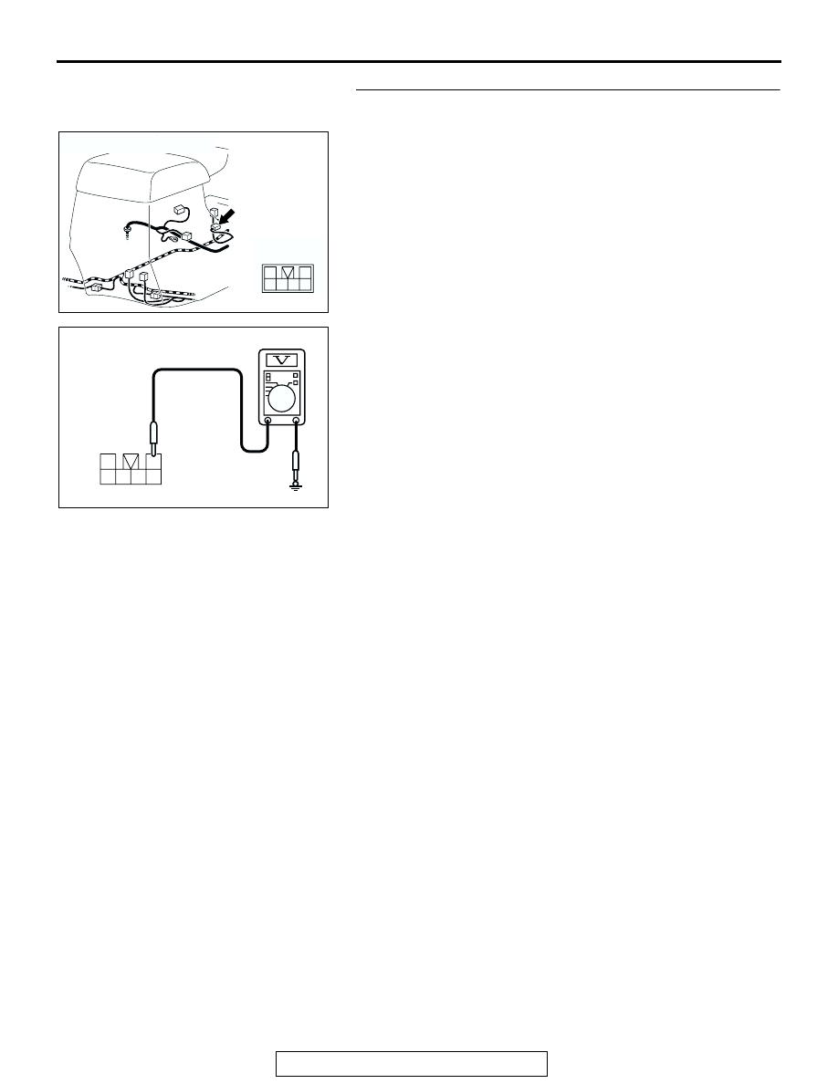
STEP 3. Measure the power supply voltage at transfer shift 
lever switch connector E-116.
(1) Disconnect connector E-116 and measure at harness side.
(2) Turn the ignition switch to the "ON" position.

(3) Measure the voltage between terminal 1 and ground.

• The voltage should measure battery positive voltage.

(4) Turn the ignition switch to the "LOCK" (OFF) position.
Q: Is the measured voltage battery positive voltage?

YES : Go to Step 6.
NO :  Go to Step 4.

AC204175

CONNECTOR : E-116

AH

6

2

5

4

3

1

AC204918 CI

E-116 HARNESS CONNECTOR : 
COMPONENT SIDE

3

1

4

5

6

2

TRANSFER DIAGNOSIS <ACTIVE TRAC AWD II>

TSB Revision

AUTOMATIC TRANSMISSION

23A-452

STEP 4. Check joint connector D-01, junction block 
connector D-208, D-212, intermediate connector E-11 and 
transfer shift lever switch connector E-116 for loose, 
corroded or damaged terminals, or terminals pushed back 
in the connector.

AC204170

CONNECTOR : D-01

CD

9 10

8

6 7

31 32

30

29

18 19 20 21

5

4

2

1

3

27

26

24

23

25

12 13 14 15 16 17

28

11
22
33

AC204191

CONNECTORS : D-208, D-212

5 6

2

4

3

1

JUNCTION BLOCK
(FRONT VIEW)

3

10

9

4

11

8

7

1

5

2

6

D-208

D-208

D-212

D-212

AS

AC204176

CONNECTOR : E-11

AZ

3

10

16

9

7 8

6

1

4

2

5

11

14

1213

15

TRANSFER DIAGNOSIS <ACTIVE TRAC AWD II>

TSB Revision

AUTOMATIC TRANSMISSION

23A-453

Q: Are the connectors and terminals in good condition?

YES : Go to Step 5.
NO :  Repair or replace the damaged components. Refer to 

GROUP 00E, Harness Connector Inspection 

P.00E-2

.

STEP 5. Check harness for open circuit or short circuit to 
ground between junction block connector D-208 terminal 2 
and transfer shift lever switch connector E-116 terminal 1.
Q: Is the harness wire in good condition?

YES : Go to Step 10.
NO :  Repair or replace the harness wire.

AC204175

CONNECTOR : E-116

AH

6

2

5

4

3

1

AC204173

CONNECTOR : D-208

BA

5 6

2

4

3

1

JUNCTION BLOCK
(FRONT VIEW)

AC204175

CONNECTOR : E-116

AH

6

2

5

4

3

1

TRANSFER DIAGNOSIS <ACTIVE TRAC AWD II>

TSB Revision

AUTOMATIC TRANSMISSION

23A-454

STEP 6. Measure the switch output voltage at transfer-ECU 
connector E-109 by backprobing.
(1) Disconnect connector E-109 and measure at the harness 

side.

(2) Turn the ignition switch to the "ON" position.

(3) Measure the voltage between terminal 20 (Transfer shift 

lever position: 2H) and ground by backprobing. [terminal 21 
(Transfer shift lever position: 4H), terminal 22 (Transfer shift 
lever position: 4HLc), terminal 23 (Transfer shift lever 
position: 4LLc) and ground by backprobing.]

• The voltage should measure battery positive voltage.

(4) Turn the ignition switch to the "LOCK" (OFF) position.
Q: Is the measured voltage battery positive voltage?

YES : Go to Step 9.
NO :  Go to Step 7.

STEP 7. Check transfer-ECU connector E-109 and transfer 
shift lever switch connector E-116 for loose, corroded or 
damaged terminals, or terminals pushed back in the 
connector.
Q: Are the connectors and terminals in good condition?

YES : Go to Step 8.
NO :  Repair or replace the damaged components. Refer to 

GROUP 00E, Harness Connector Inspection 

P.00E-2

.

AC204176

CONNECTOR : E-109

BB

11 12

25

24

13

26

9

22

7

6

20

19

8

21

10

23

5

4

17

2

1

15

14

3

16

18

AC204918 CG

E-109 HARNESS CONNECTOR : 
HARNESS SIDE

11 12

25

24

13

26

9

22

7

6

20

19

8

21

10

23

5

4

17

2

1

15

14

3

16

18

AC204176

CONNECTOR : E-109

BB

11 12

25

24

13

26

9

22

7

6

20

19

8

21

10

23

5

4

17

2

1

15

14

3

16

18

AC204175

CONNECTOR : E-116

AH

6

2

5

4

3

1


Content   ..  967  968  969  970   ..