Mitsubishi Montero (2004+). Manual - part 841


  Index      Mitsubishi     Mitsubishi Montero - service repair manual 2004 year


Search            


Content   ..  839  840  841  842   ..


Mitsubishi Montero (2004+). Manual - part 841


INPUT SIGNAL PROCEDURES

TSB Revision

SIMPLIFIED WIRING SYSTEM (SWS)

54B-621

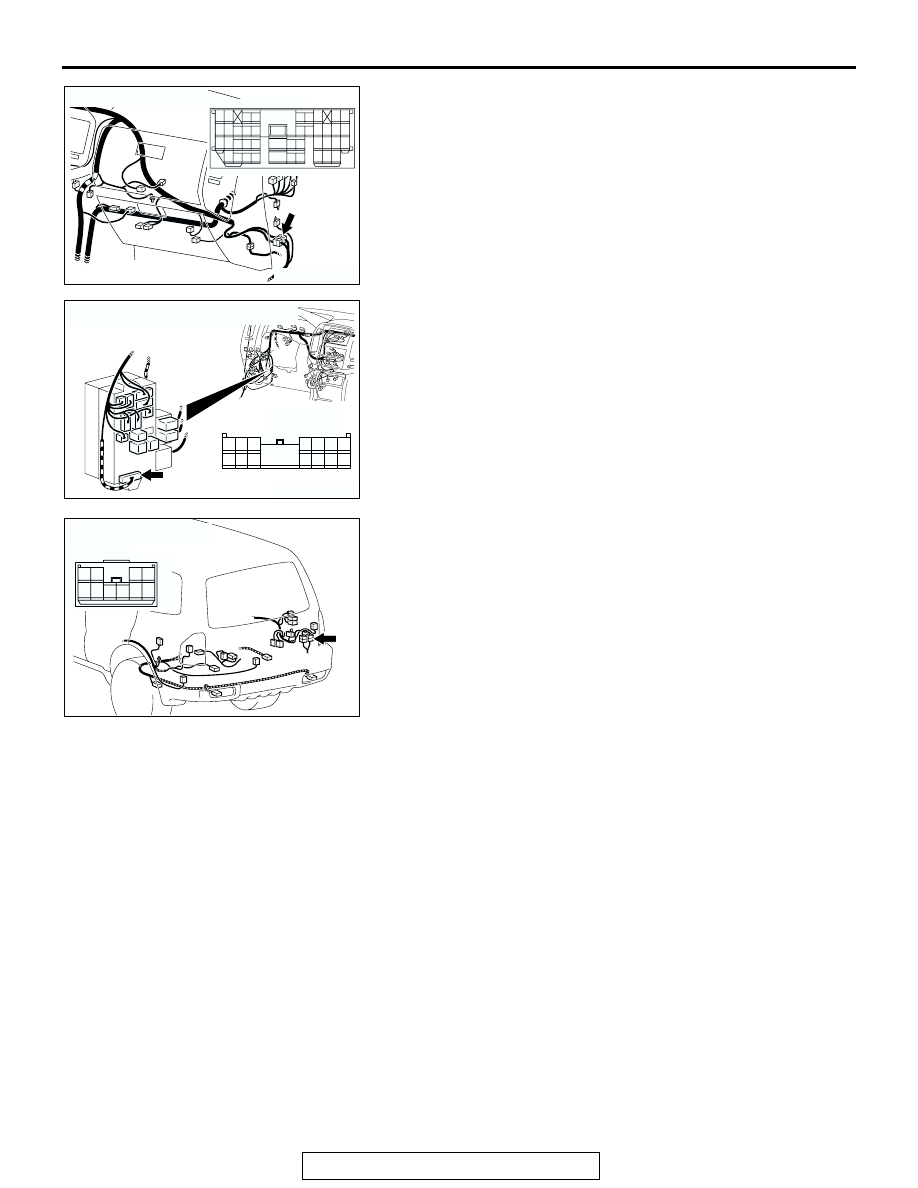
NOTE: Also check intermediate connectors D-111, G-10 and 
junction block connector D-217 for loose, corroded, or dam-
aged terminals, or terminals pushed back in the connector. If 
intermediate connector D-111, G-10 or junction block connector 
D-217 is damaged, Repair or replace the damaged compo-
nent(s) as described in GROUP 00E, Harness Connector 
Inspection 

P.00E-2

Q: Is the wiring harness between rear wiper motor 

connector I-07 (terminal 3) and ETACS-ECU connector 
D-222 (terminal 5) in good condition?
YES : 
Replace the ETACS-ECU. If the rear wiper operates 

normally, it indicates that a correct auto-stop signal is 
sent from the rear wiper motor.

NO :  The wiring harness may be damaged or the 

connector(s) may have loose, corroded or damaged 
terminals, or terminals pushed back in the connector. 
Repair the wiring harness as necessary. If the rear 
wiper operates normally, it indicates that a correct 
auto-stop signal is sent from the rear wiper motor.

AC204171

CONNECTOR : D-111

BH

9

8

6 7

5

3 4

20

32

21

33

43

17 18

30

41

16

29

28

39 40

13

25

12

24

35 36

14

26

37

15

27

38

19

31

42

1

10

22

2

11

23

34

AC204173

CONNECTOR : D-217

AG

HARNESS SIDE

8

1

11 10

3

4

12

9

2

13

14

6 5

15

7

D-217

AC204179

CONNECTOR : G-10

AD

4

10

8

7

3

9

5

1

6

2

INPUT SIGNAL PROCEDURES

TSB Revision

SIMPLIFIED WIRING SYSTEM (SWS)

54B-622

INSPECTION PROCEDURE P-9: ETACS-ECU does not receive any signal from hood switch.

.

CIRCUIT OPERATION
The ETACS-ECU operates the theft-alarm system 
according to signal from the hood switch.

.

TECHNICAL DESCRIPTION (COMMENT)
If the signal is not normal, the theft-alarm system 
does not work normally.

.

TROUBLESHOOTING HINTS

• The hood switch may be defective

• The ETACS-ECU may be defective

Hood Switch Input Circuit

AC204167

CONNECTOR : A-14

A-14(B)

AL

AC204170

CONNECTOR : D-27

BA

AC204174

CONNECTOR : D-223

D-223(B)

AF

INPUT SIGNAL PROCEDURES

TSB Revision

SIMPLIFIED WIRING SYSTEM (SWS)

54B-623

• The wiring harness or connectors may have 

loose, corroded, or damaged terminals, or termi-
nals pushed back in the connector

DIAGNOSIS

Required Special Tools:

• MB991223: Harness Set

• MB991958: Scan Tool (MUT-III Sub Assembly)

• MB991824: Vehicle Communication Interface (V.C.I.)

• MB991827: MUT-III USB Cable

• MB991911: MUT-III Main Harness B

STEP 1. Check hood switch connector A-14 for loose, 
corroded or damaged terminals, or terminals pushed back 
in the connector.
Q: Is hood switch connector A-14 in good condition? 

YES : Go to Step 2.
NO :  Repair or replace the damaged component(s). Refer 

to GROUP 00E, Harness Connector Inspection 

P.00E-2

. If the theft-alarm system operates normally, 

it indicates that a correct signal is sent from the hood 
switch.

STEP 2. Check the hood switch.
Remove the hood switch. Then check continuity between the 
switch terminals.

Q: Is the hood switch in good condition?

YES : Go to Step 3.
NO :  Replace the hood switch. If the theft-alarm system 

operates normally, it indicates that a correct signal is 
sent from the hood switch.

AC204167

CONNECTOR : A-14

HARNESS 
SIDE

A-14(B)

A-14(B)

AC

1

2

SWITCH 
POSITION

TESTER 
CONNECTION

SPECIFIED 
CONDITION

Released

− 2

Less than 2 ohms

Pressed

− 2

Open circuit

1

2

ACX02415

INPUT SIGNAL PROCEDURES

TSB Revision

SIMPLIFIED WIRING SYSTEM (SWS)

54B-624

STEP 3. Check the ground circuit to the hood switch. Test 
at hood switch connector A-14.
(1) Disconnect hood switch connector A-14 and measure the 

resistance available at the wiring harness side of the 
connector.

(2) Measure the resistance value between terminal 2 and 

ground.

• The resistance should equal 2 ohms or less.

Q: Is the measured resistance 2 ohms or less?

YES : Go to Step 5.
NO :  Go to Step 4.

STEP 4. Check the wiring harness between hood switch 
connector A-14 (terminal 2) and ground.
Q: Is the wiring harness between hood switch connector 

A-14 (terminal 2) and the ground in good condition?
YES : 
No action is necessary and testing is complete.
NO :  The wiring harness may be damaged or the 

connector(s) may have loose, corroded or damaged 
terminals, or terminals pushed back in the connector. 
Repair the wiring harness as necessary. If the 
theft-alarm system operates normally, it indicates that 
a correct signal is sent from the hood switch.

AC204167

CONNECTOR : A-14

HARNESS 
SIDE

A-14(B)

A-14(B)

AC

1

2

2 1

ACX01608AB

CONNECTOR A-14
(HARNESS SIDE)

AC204167

CONNECTOR : A-14

HARNESS 
SIDE

A-14(B)

A-14(B)

AC

1

2


Content   ..  839  840  841  842   ..