Mitsubishi Montero (2004+). Manual - part 840


  Index      Mitsubishi     Mitsubishi Montero - service repair manual 2004 year


Search            


Content   ..  838  839  840  841   ..


Mitsubishi Montero (2004+). Manual - part 840


INPUT SIGNAL PROCEDURES

TSB Revision

SIMPLIFIED WIRING SYSTEM (SWS)

54B-617

STEP 1. Check rear wiper motor connector I-07 for loose, 
corroded or damaged terminals, or terminals pushed back 
in the connector.
Q: Is rear wiper motor connector I-07 in good condition?

YES : Go to Step 2.
NO :  Repair or replace the damaged component(s). Refer 

to GROUP 00E, Harness Connector Inspection 

P.00E-2

If the rear wiper operates normally, it 

indicates that a correct auto-stop signal is sent from 
the rear wiper motor.

STEP 2. Check the rear wiper.
Q: Does the rear wiper motor operate (however, the rear 

wiper does not stop at the predetermined park 
position)?
YES : 
Go to Step 3.
NO :  Refer to Inspection Procedure H-1 "Rear wiper dose 

not work at all 

P.54B-265

."

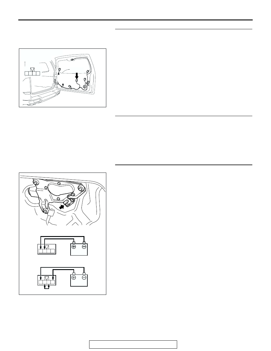
STEP 3. Check the rear wiper motor.
(1) Disconnect rear wiper motor connector I-07.
(2) While the rear wiper motor is running, disconnect the 

battery to stop the motor.

(3) When the battery is connected as shown, the motor should 

run again and stop at the predetermined park position.

Q: Does the rear wiper motor operate normally?

YES : Go to Step 4.
NO :  Replace the rear wiper motor. If the rear wiper 

operates normally, it indicates that a correct auto-stop 
signal is sent from the rear wiper motor.

AC204182

CONNECTOR : I-07

AE

HARNESS SIDE

I-07(B)

I-07(B)

1

2

4 3

1 2 3 4

1 2 3 4

ACX00453

OPERATION CHECK

AB

STOP POSITION CHECK

INPUT SIGNAL PROCEDURES

TSB Revision

SIMPLIFIED WIRING SYSTEM (SWS)

54B-618

STEP 4. Check the ignition switch (ACC) line of the power 
supply circuit to the rear wiper motor. Test at rear wiper 
motor connector I-07.
(1) Disconnect rear wiper motor connector I-07 and measure 

the voltage available at the wiring harness side of the 
connector.

(2) Turn the ignition switch to the "ACC" position.

(3) Measure the voltage between terminal 4 and ground.

• The voltage should equal approximately 12 volts (bat-

tery positive voltage).

Q: Is the measured voltage approximately 12 volts (battery 

positive voltage)?
YES : 
Go to Step 6.
NO :  Go to Step 5.

STEP 5. Check the wiring harness between rear wiper 
motor connector I-07 (terminal 4) and the ignition switch 
(ACC).

AC204182

CONNECTOR : I-07

AE

HARNESS SIDE

I-07(B)

I-07(B)

1

2

4 3

4 3 2 1

AC204537

CONNECTOR I-07
(HARNESS SIDE)

AB

AC204182

CONNECTOR : I-07

AE

HARNESS SIDE

I-07(B)

I-07(B)

1

2

4 3

INPUT SIGNAL PROCEDURES

TSB Revision

SIMPLIFIED WIRING SYSTEM (SWS)

54B-619

NOTE: Also check intermediate connectors D-111, G-10, junc-
tion block connectors D-208 and D-217 for loose, corroded, or 
damaged terminals, or terminals pushed back in the connector. 
If intermediate connector D-111, G-10, junction block connector 
D-208 or D-217 is damaged, Repair or replace the damaged 
component(s) as described in GROUP 00E, Harness Connec-
tor Inspection 

P.00E-2

Q: Is the wiring harness between rear wiper motor 

connector I-07 (terminal 4) and the ignition switch (ACC) 
in good condition?
YES : 
No action is necessary and testing is complete.
NO :  The wiring harness may be damaged or the 

connector(s) may have loose, corroded or damaged 
terminals, or terminals pushed back in the connector. 
Repair the wiring harness as necessary. If the rear 
wiper operates normally, it indicates that a correct 
auto-stop signal is sent from the rear wiper motor.

AC204171

CONNECTOR : D-111

BH

9

8

6 7

5

3 4

20

32

21

33

43

17 18

30

41

16

29

28

39 40

13

25

12

24

35 36

14

26

37

15

27

38

19

31

42

1

10

22

2

11

23

34

AC204191

CONNECTORS : D-208, D-217

D-208

AE

HARNESS SIDE

HARNESS SIDE

D-217

D-208

D-217

1

2

3

5

6

4

8

1

11 10

3

4

12

9

2

13

14

6 5

15

7

AC204179

CONNECTOR : G-10

AD

4

10

8

7

3

9

5

1

6

2

INPUT SIGNAL PROCEDURES

TSB Revision

SIMPLIFIED WIRING SYSTEM (SWS)

54B-620

STEP 6. Check ETACS-ECU connector D-222 for loose, 
corroded or damaged terminals, or terminals pushed back 
in the connector.
Q: Are rear ETACS-ECU connector D-222 in good 

condition?
YES : 
Go to Step 7.
NO :  Repair or replace the damaged component(s). Refer 

to GROUP 00E, Harness Connector Inspection 

P.00E-2

If the rear wiper operates normally, it 

indicates that a correct auto-stop signal is sent from 
the rear wiper motor.

STEP 7. Check the wiring harness between rear wiper 
motor connector I-07 (terminal 3) and ETACS-ECU 
connector D-222 (terminal 5).

AC204174

CONNECTOR : D-222

AB

1

2

3

5

6

4

9 8

121110

13

15 14

16

17

7

19

20

18

JUNCTION BLOCK SIDE

D-222

AC204174

CONNECTOR : D-222

AB

1

2

3

5

6

4

9 8

121110

13

15 14

16

17

7

19

20

18

JUNCTION BLOCK SIDE

D-222

AC204182

CONNECTOR : I-07

AE

HARNESS SIDE

I-07(B)

I-07(B)

1

2

4 3


Content   ..  838  839  840  841   ..