Mitsubishi Montero (2004+). Manual - part 789
SYMPTOM PROCEDURES
TSB Revision
SIMPLIFIED WIRING SYSTEM (SWS)
54B-413
.
TECHNICAL DESCRIPTION (COMMENT)
If one of the fog lights does not illuminate, the fog
light relay or the fog light bulb may be defective. If
the fog light indicator light does not illuminate, the
combination meter may be defective.
.
TROUBLESHOOTING HINTS
• The fog light bulb may be defective
• The combination meter may be defective
• The wiring harness or connectors may have
loose, corroded, or damaged terminals, or termi-
nals pushed back in the connector
.
DIAGNOSIS
Required Special Tool:
• MB991223: Harness Set
STEP 1. Verify that the fog lights and the fog light indicator
light illuminate.
Q: Which light does not illuminate?
Fog light (LH) : Go to Step 2.
Fog light (RH) : Go to Step 8.
Fog light indicator : Go to Step 14.
Fog lights (both RH and LH) : Go to Step 20.
All lights : Refer to Inspection procedure L-1 "Fog lights do
not illuminate when the fog light switch is turned on
AC204183
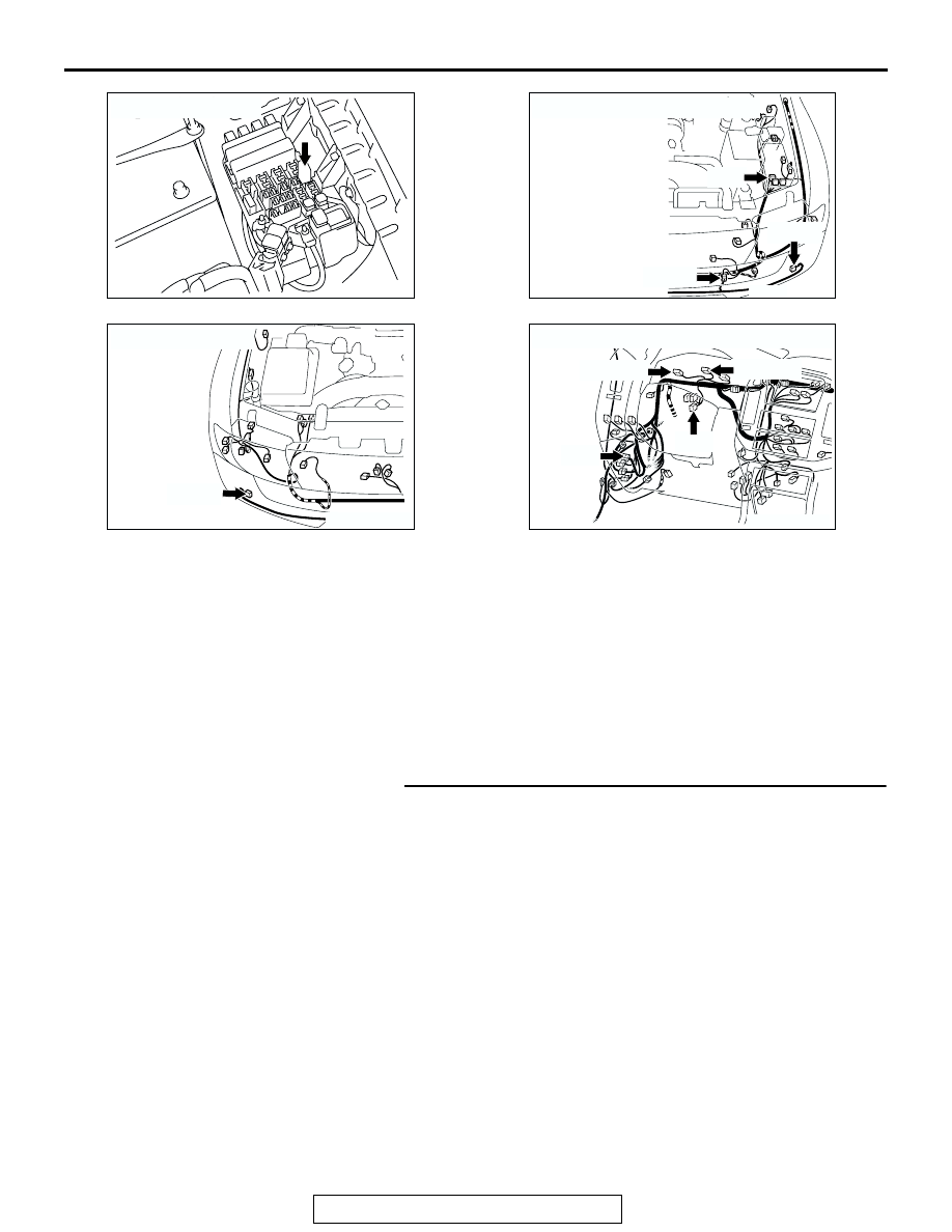
CONNECTOR : A-13X
AH
AC204167
CONNECTORS : A-15, A-21, A-25
A-15
AQ
A-25(B)
A-21(B)
AC204166
CONNECTOR : A-31
AL
A-31(B)
AC204170
CONNECTORS : D-03, D-04, D-28, D-30
BL
D-03(GR)
D-04(GR)
D-28
D-30