Mitsubishi Montero (2004+). Manual - part 787
SYMPTOM PROCEDURES
TSB Revision
SIMPLIFIED WIRING SYSTEM (SWS)
54B-405
.
CIRCUIT OPERATION
• The ETACS-ECU sends a fog light illumination
request signal ("LIGHT ON" signal) to the
front-ECU when the fog light switch is turned on
while the headlights are on.
• Then the front-ECU switches on its relay to illumi-
nate the fog lights.
.
TECHNICAL DESCRIPTION (COMMENT)
If the headlights illuminate normally, the fog light
relay, the fog light switch, the front-ECU or the
ETACS-ECU may be defective.
.
TROUBLESHOOTING HINTS
• The fog light relay may be defective
• The fog light switch may be defective
• The front-ECU may be defective
• The ETACS-ECU may be defective
• The wiring harness or connectors may have
loose, corroded, or damaged terminals, or termi-
nals pushed back in the connector
DIAGNOSIS
Required Special Tools:
• MB991223: Harness Set
• MB991958: Scan Tool (MUT-III Sub Assembly)
• MB991824: Vehicle Communication Interface (V.C.I.)
• MB991827: MUT-III USB Cable
• MB991911: MUT-III Main Harness B
• MB991813: SWS Monitor Kit
• MB991806: SWS Monitor Cartridge
• MB991812: SWS Monitor Harness (For Column-ECU)
• MB991822: Probe Harness
STEP 1. Verify the headlight operation.
Q: Do the headlights illuminate normally?
The lights illuminate normally at both high and low
beams : Go to Step 2.
Headlights do not Illuminate at low beam : Refer to
Inspection Procedure J-2 "Headlights (low-beam) do
not illuminate normally
Headlights do not Illuminate at high beam : Refer to
Inspection Procedure J-3 "Headlights (high-beam) do
not illuminate normally
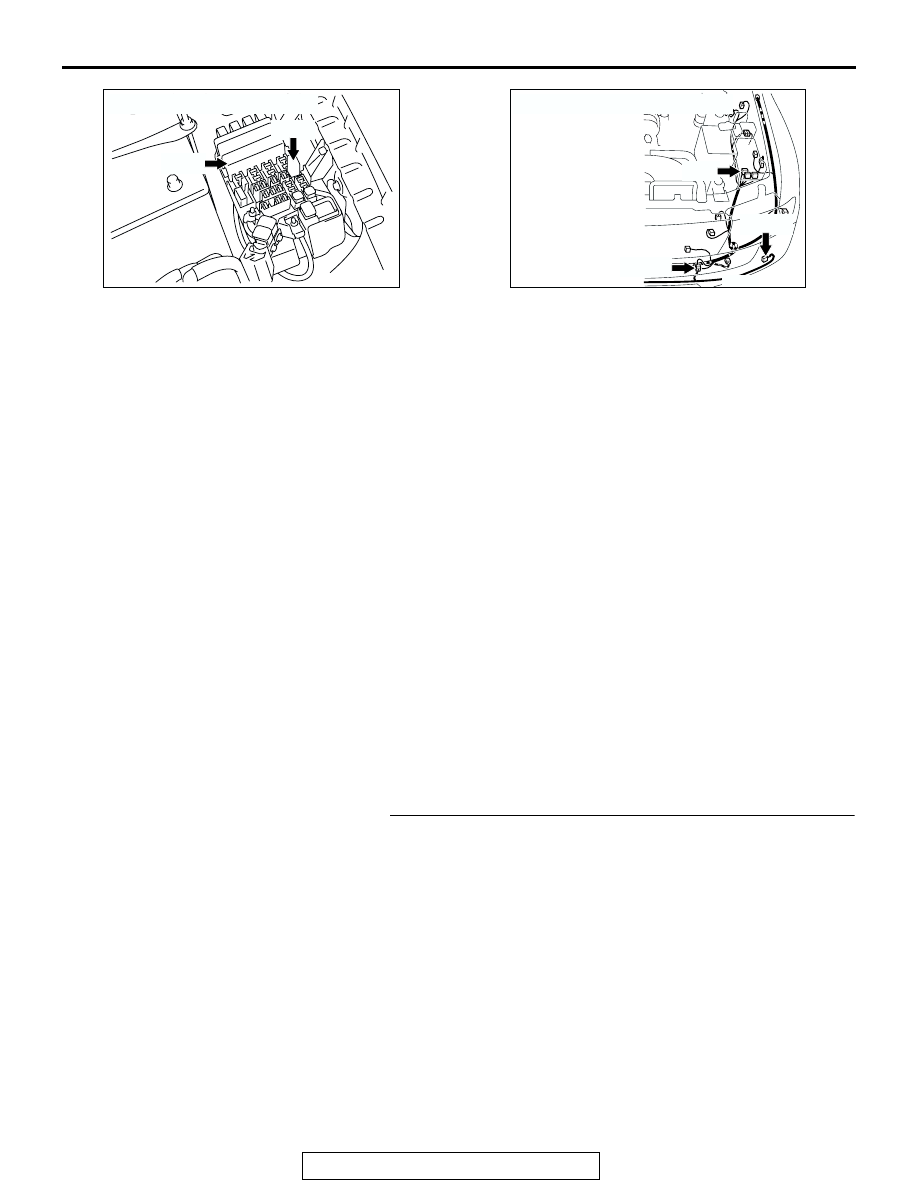
AC204183
CONNECTORS : A-07X, A-13X
A-13X
A-07X
AJ
AC204167
CONNECTORS : A-15, A-21, A-25
A-15
AQ
A-25(B)
A-21(B)