Mitsubishi Montero (2004+). Manual - part 788


  Index      Mitsubishi     Mitsubishi Montero - service repair manual 2004 year


Search            


Content   ..  786  787  788  789   ..


Mitsubishi Montero (2004+). Manual - part 788


SYMPTOM PROCEDURES

TSB Revision

SIMPLIFIED WIRING SYSTEM (SWS)

54B-409

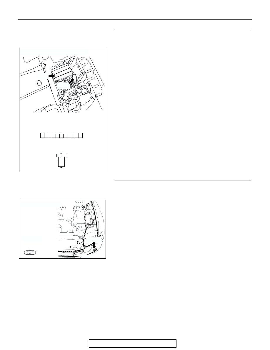
STEP 8. Check the wiring harness between fog light relay 
connector A-13X (terminal 1) and front-ECU connector 
A-07X (terminal 1).
Q: Is the wiring harness between fog light relay connector 

A-13X (terminal 1) and front-ECU connector A-07X 
(terminal 1) in good condition?
YES : 
Go to Step 9.
NO :  The wiring harness may be damaged or the 

connector(s) may have loose, corroded or damaged 
terminals, or terminals pushed back in the connector. 
Repair the wiring harness as necessary. Verify that 
the fog lights illuminate normally.

STEP 9. Check fog light (LH) connector A-21 for loose, 
corroded or damaged terminals, or terminals pushed back 
in the connector.
Q: Is fog light (LH) connector A-21 in good condition?

YES : Go to Step 10.
NO :  Repair or replace the damaged component(s). Refer 

to GROUP 00E, Harness Connector Inspection 

P.00E-2

. Verify that the fog lights illuminate normally.

AC204201

RELAY BOX SIDE

A-13X

RELAY BOX SIDE

A-07X

2 1

5

4

3

CONNECTORS : A-07X, A-13X

A-07X

AB

A-13X

2 1

3

4

6

7

8

9

5

11 10

AC204167

CONNECTOR : A-21

HARNESS 
SIDE

A-21(B)

A-21(B)

AJ

1

2

SYMPTOM PROCEDURES

TSB Revision

SIMPLIFIED WIRING SYSTEM (SWS)

54B-410

STEP 10. Check the wiring harnesses among fog light 
relay connector A-13X (terminal 5) and fog light (LH) 
connector A-21 (terminal 1).

NOTE: Also check joint connector A-15 and intermediate con-
nector A-25 for loose, corroded, or damaged terminals, or ter-
minals pushed back in the connector. If joint connector A-15 or 
intermediate connectors A-25 is damaged, repair or replace the 
damaged component(s) as described in GROUP 00E, Harness 
Connector Inspection 

P.00E-2

.

Q: Are the wiring harnesses among fog light relay 

connector A-13X (terminal 5) and fog light (LH) 
connector A-21 (terminal 1) in good condition?
YES : 
Go to Step 11.
NO :  The wiring harness may be damaged or the 

connector(s) may have loose, corroded or damaged 
terminals, or terminals pushed back in the connector. 
Repair the wiring harness as necessary. Verify that 
the fog lights illuminate normally.

AC204183

CONNECTOR : A-13X

RELAY BOX SIDE

AF

2 1

5

4

3

A-13X

AC204185

CONNECTORS : A-15, A-21, A-25

A-21(B)

A-15

AC

A-15

A-25

HARNESS SIDE

A-21(B)

A-25(B)

14

13

4

1112

5

3

10

8 9

2

7

1

6

1

2

4

2

3

1

SYMPTOM PROCEDURES

TSB Revision

SIMPLIFIED WIRING SYSTEM (SWS)

54B-411

STEP 11. Replace the ECU.
(1) Replace the front-ECU.
(2) Verify that the fog lights illuminate normally.
Q: Do the fog lights illuminate normally?

YES : No action is necessary and testing is complete.
NO :  Replace the ETACS-ECU. Verify that the fog lights 

illuminate normally.

INSPECTION PROCEDURE L-2: Fog Light: Fog lights do not go out when the headlights (low-beam) 
are turned off while the fog lights are on.

.

TECHNICAL DESCRIPTION (COMMENT)
If the trouble above occurs, the front-ECU may be 
defective.

.

TROUBLESHOOTING HINT
The front-ECU may be defective

DIAGNOSIS

Replace the front-ECU.
The fog lights should go out when the headlights (low-beam) 
are turned off while the fog lights are on.

SYMPTOM PROCEDURES

TSB Revision

SIMPLIFIED WIRING SYSTEM (SWS)

54B-412

INSPECTION PROCEDURE L-3: Fog Light: One of the fog lights does not illuminate.

Fog Light Circuit


Content   ..  786  787  788  789   ..