Mitsubishi Montero (2004+). Manual - part 779


  Index      Mitsubishi     Mitsubishi Montero - service repair manual 2004 year


Search            


Content   ..  777  778  779  780   ..


Mitsubishi Montero (2004+). Manual - part 779


SYMPTOM PROCEDURES

TSB Revision

SIMPLIFIED WIRING SYSTEM (SWS)

54B-373

.

CIRCUIT OPERATION

• The turn-signal light switch sends any signal 

through the column-ECU (incorporated in the col-
umn switch) to the ETACS-ECU. If the col-
umn-ECU sends a turn-signal light switch "ON" 
signal to the ETACS-ECU, the ETACS-ECU turns 
on the flasher timer (incorporated in the 
ETACS-ECU), thus causing the turn-signal lights 
to flash.

• The ETACS-ECU operates the turn-signal lights 

according to the following signals:

• Ignition switch (IG1)

• Turn-signal light switch

.

TECHNICAL DESCRIPTION (COMMENT)
Is the turn-signal lights do not flash normally, the 
input circuits from the switches described in "CIR-
CUIT OPERATION" or the ETACS-ECU may be 
defective. If the hazard warning lights do not flash, 
the power supply line to the ETACS-ECU (dedicated 
to the turn-signal lights) may be defective.

.

TROUBLESHOOTING HINTS

• The column switch (turn-signal light and lighting 

switch) may be defective

• The ETACS-ECU may be defective

• The wiring harness or connectors may have 

loose, corroded, or damaged terminals, or termi-
nals pushed back in the connector

DIAGNOSIS

Required Special Tools:

• MB991223: Harness Set

• MB991958: Scan Tool (MUT-III Sub Assembly)

• MB991824: Vehicle Communication Interface (V.C.I.)

• MB991827: MUT-III USB Cable

• MB991911: MUT-III Main Harness B

• MB991813: SWS Monitor Kit

• MB991806: SWS Monitor Cartridge

• MB991812: SWS Monitor Harness (For Column-ECU)

• MB991822: Probe Harness
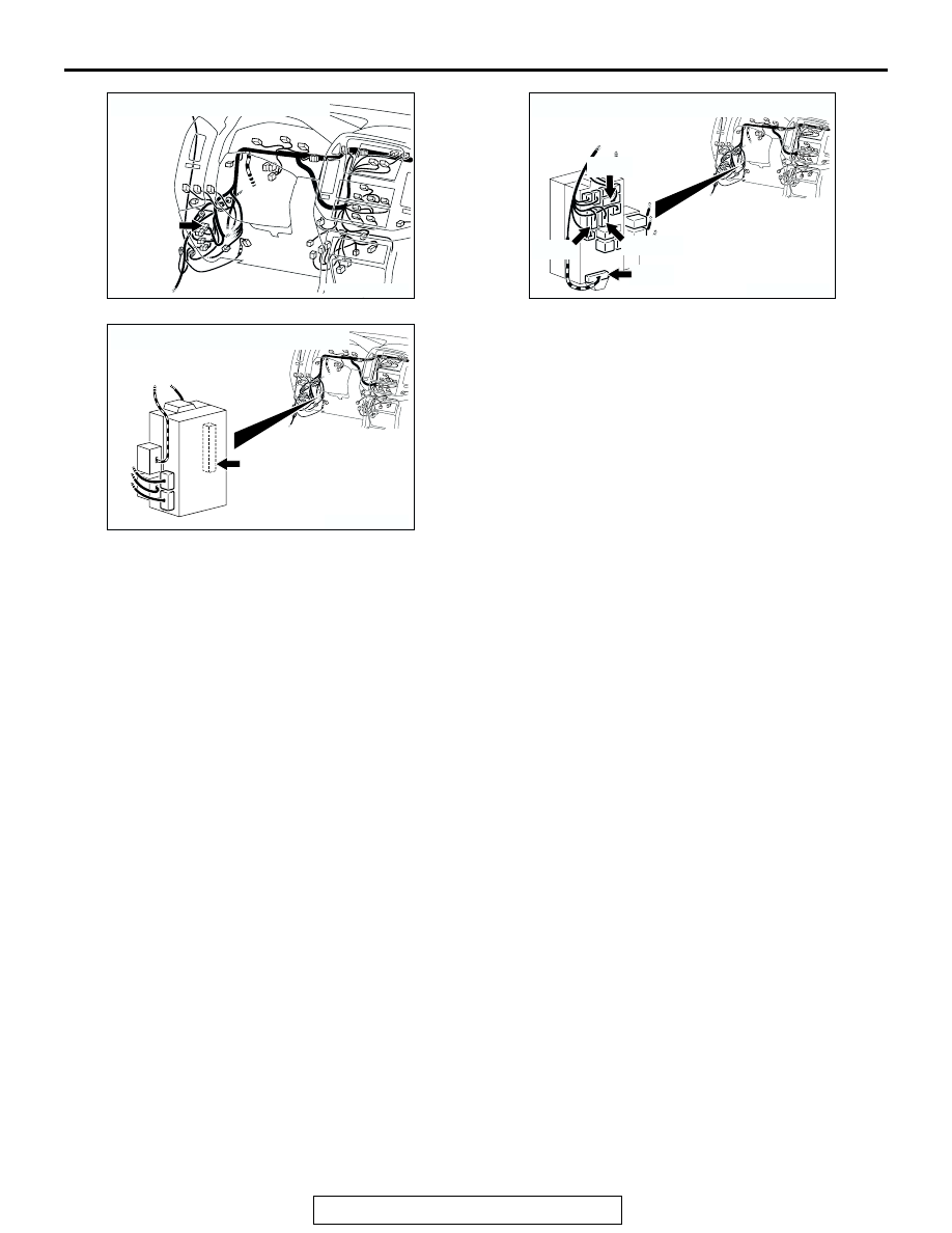
AC204170

CONNECTOR : D-28

BB

AC204173

CONNECTORS : D-210, D-212, D-217, D-221

D-210

D-217

D-212

AW

D-221

AC204174

CONNECTOR : D-222            

AE

SYMPTOM PROCEDURES

TSB Revision

SIMPLIFIED WIRING SYSTEM (SWS)

54B-374

STEP 1. Verify the hazard warning light operation.
Q: Does the hazard warning light work normally?

YES : Go to Step 7.
NO :  Go to Step 2.

STEP 2. Verify the turn-signal light operation.
Q: Does either of the turn-signal lights illuminate?

YES (illuminates at only one side) : Go to Step 3.
NO (do not illuminate at all) : Go to Step 4.

STEP 3. Check ETACS-ECU connector D-222, junction 
block connectors D-210, D-212 and D-217 for loose, 
corroded or damaged terminals, or terminals pushed back 
in the connector.
Q: Are ETACS-ECU connector D-222, junction block 

connectors D-210, D-212 and D-217 in good condition?
YES : 
Replace the ETACS-ECU. Verify that the turn-signal 

lights illuminate normally.

NO :  Repair or replace the damaged component(s). Refer 

to GROUP 00E, Harness Connector Inspection 

P.00E-2

Verify that the turn-signal lights illuminate 

normally.

AC204191

CONNECTORS : D-210, D-212, D-217

D-210

AG

HARNESS SIDE

HARNESS SIDE

D-217

D-210

HARNESS SIDE

D-212

D-212

D-217

1

2

7 6

3

9

4

11

12

10

13

5

8

8

1

11 10

3

4

12

9

2

13

14

6 5

15

7

7 6 5

2 1

9 8

11 10

4 3

AC204174

CONNECTOR : D-222

AB

1

2

3

5

6

4

9 8

121110

13

15 14

16

17

7

19

20

18

JUNCTION BLOCK SIDE

D-222

SYMPTOM PROCEDURES

TSB Revision

SIMPLIFIED WIRING SYSTEM (SWS)

54B-375

STEP 4. Check ETACS-ECU connector D-222 for loose, 
corroded or damaged terminals, or terminals pushed back 
in the connector.
Q: Is ETACS-ECU connector D-222 in good condition?

YES : Go to Step 5.
NO :  Repair or replace the damaged component(s). Refer 

to GROUP 00E, Harness Connector Inspection 

P.00E-2

Verify that the turn-signal lights illuminate 

normally.

STEP 5. Check the battery power supply circuit to the 
ETACS-ECU. Test at ETACS-ECU connector D-222.
(1) Disconnect ETACS-ECU connector D-222 and measure the 

voltage available at the junction block side of the connector.

(2) Measure the voltage between terminal 11 and ground.

• The voltage should be approximately 12 volts (battery 

positive voltage).

Q: Is the measured voltage approximately 12 volts (battery 

positive voltage)?
YES : 
Replace the ETACS-ECU. Verify that the turn-signal 

lights illuminate normally.

NO :  Go to Step 6.

STEP 6. Check the wiring harness between ETACS-ECU 
connector D-222 (terminal 11) and the battery.

AC204174

CONNECTOR : D-222

AB

1

2

3

5

6

4

9 8

121110

13

15 14

16

17

7

19

20

18

JUNCTION BLOCK SIDE

D-222

AC204174

CONNECTOR : D-222

AB

1

2

3

5

6

4

9 8

121110

13

15 14

16

17

7

19

20

18

JUNCTION BLOCK SIDE

D-222

ACX01589

19

20

1817 1615 141312 1110 9 8 7

6 5 4 3 2 1

AB

CONNECTOR D-222
(JUNCTION BLOCK SIDE)

AC204174

CONNECTOR : D-222

AB

1

2

3

5

6

4

9 8

121110

13

15 14

16

17

7

19

20

18

JUNCTION BLOCK SIDE

D-222

SYMPTOM PROCEDURES

TSB Revision

SIMPLIFIED WIRING SYSTEM (SWS)

54B-376

NOTE: Also check intermediate connector D-28 and junction 
block connector D-221 for loose, corroded, or damaged termi-
nals, or terminals pushed back in the connector. If intermediate 
connector D-28 or junction block connector D-221 is damaged, 
repair or replace the damaged component(s) as described in 
GROUP 00E, Harness Connector Inspection 

P.00E-2

.

Q: Is the wiring harness between ETACS-ECU connector 

D-222 (terminal 11) and the battery in good condition?
YES : 
No action is necessary and testing is complete.
NO :  The wiring harness may be damaged or the 

connector(s) may have loose, corroded or damaged 
terminals, or terminals pushed back in the connector. 
Repair the wiring harness as necessary. Verify that 
the turn-signal lights illuminate normally.

AC204170

CONNECTOR : D-28

AI

2 3

27

32

28

33

16

15

4 5

19

18

29

17

34

7 8

35

22

21

9 10

30

36

31

37

25

24

23

6

20

1

14

26

11

13

12

38

AC204173

CONNECTOR : D-221

AJ

HARNESS SIDE

3

1

4

6 5

7

8

2


Content   ..  777  778  779  780   ..