Mitsubishi Montero (2004+). Manual - part 777


  Index      Mitsubishi     Mitsubishi Montero - service repair manual 2004 year


Search            


Content   ..  775  776  777  778   ..


Mitsubishi Montero (2004+). Manual - part 777


SYMPTOM PROCEDURES

TSB Revision

SIMPLIFIED WIRING SYSTEM (SWS)

54B-365

STEP 2. Check the input signal by using "FUNCTION 
DIAG." menu of the SWS monitor.
Check the input signals from the following switches:

• Ignition switch: "ON" to "OFF"

• Lighting switch: "TAIL" or "HEAD"

CAUTION

To prevent damage to scan tool MB991958, always turn the 
ignition switch to the "LOCK" (OFF) position before con-
necting or disconnecting scan tool MB991958.
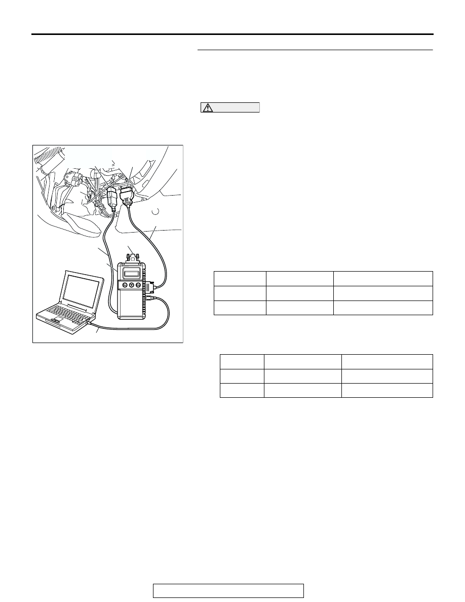
(1) Connect the special tool. Refer to "How to connect SWS 

monito

P.54B-7

.

(2) Operate scan tool MB991958 according to the procedure 

below to display "H/L AUTO-CUT."

1. Select "SYSTEM SELECT."
2. Select "SWS."
3. Select "SWS MONITOR."
4. Select "FUNCTION DIAG."
5. Select "LIGHTING."
6. Select "H/L AUTO-CUT."

(3) Check that normal conditions are displayed on the items 

described in the table below.

(4) When the driver's door is opened, Check that normal 

conditions are displayed on the items described in the table 
below.

Q: Are normal conditions displayed on the "TAILLIGHT 

SW", "IG SW (IG1)", "FRONT DOOR SW" and "H/L 
AUTO-CUT"?
Normal conditions are displayed for all the items : 

Replace the front-ECU. Verify that the headlight 
automatic shutdown function now works normally.

Normal condition is not displayed on the "TAIL LIGHT 
SW" : 
Refer to Inspection Procedure O-6 "ETACS-ECU 

does not receive any signal from the taillight switch 

P.54B-527

."

Normal condition is not displayed on the "IG SW (IG1)" : 

Refer to Inspection Procedure O-2 "ETACS-ECU 
does not receive any signal from the ignition switch 
(IG1) 

P.54B-505

."

Normal condition is not displayed on the "FRONT 
DOOR SW" : 
Refer to Inspection Procedure O-5 

"ETACS-ECU does not receive any signal from the 

ITEM NO.

ITEM NAME

NORMAL CONDITION

ITEM 01

TAILLIGHT SW

ON

ITEM 30

IG SW (IG1)

OFF

ITEM NO. ITEM NAME

NORMAL CONDITION

ITEM 32

FRONT DOOR SW ON

ITEM 35

H/L AUTO-CUT

ON

AC309091

MB991911

MB991827

MB991824 

AB

MB991806

MB991862

DATA LINK
CONNECTOR 
(16-PIN)

DATA LINK
CONNECTOR 
(13-PIN)

SYMPTOM PROCEDURES

TSB Revision

SIMPLIFIED WIRING SYSTEM (SWS)

54B-366

driver's or the front passenger's door switch 

P.54B-520

."

Normal condition is not displayed on the "H/L 
AUTO-CUT" : 
Replace the front-ECU. Verify that the 

headlight automatic shutdown function now works 
normally.

INSPECTION PROCEDURE J-10: Headlight and Taillight: Headlight dimmer switch automatic resetting 
function does not work normally.

.

CIRCUIT OPERATION
The headlight dimmer switch automatic resetting 
function is controlled by the front-ECU. 

.

TECHNICAL DESCRIPTION (COMMENT)
If the headlight dimmer switch automatic resetting 
function does not work normally, the front-ECU may 
be defective.

.

TROUBLESHOOTING HINT
The front-ECU may be defective 

DIAGNOSIS

Replace the front-ECU.
Verify that the headlight dimmer switch automatic resetting 
function now works normally.

Headlight (Dimmer/Passing) Input Signal

SYMPTOM PROCEDURES

TSB Revision

SIMPLIFIED WIRING SYSTEM (SWS)

54B-367

INSPECTION PROCEDURE J-11: Headlight and Taillight: Daytime running light function does not 
work normally. <vehicles for Canada>

.

TECHNICAL DESCRIPTION (COMMENT) 
If the daytime running light function is not operating 
normally the daytime running light-ECU power circuit 
may be defective or the daytime running light-ECU 
may be defective.

.

TROUBLESHOOTING HINTS

• The daytime running light-ECU may be defective

• The wiring harness or connectors may have 

loose, corroded, or damaged terminals, or termi-
nals pushed back in the connector

DIAGNOSIS

Required Special Tools:

• MB991223: Harness Set

• MB991958: Scan Tool (MUT-III Sub Assembly)

• MB991824: Vehicle Communication Interface (V.C.I.)

BATTERY

RELAY 
BOX

JOINT
CONNECTOR (3)

FRONT-ECU

HEADLIGHT

(LH)

FIELD EFFECT
TRANSISTOR FOR
HEADLIGHT, LOW

PULSE WIDTH
MODULATION

(RH)

Daytime Running Light Circuit

SYMPTOM PROCEDURES

TSB Revision

SIMPLIFIED WIRING SYSTEM (SWS)

54B-368

• MB991827: MUT-III USB Cable

• MB991911: MUT-III Main Harness B

• MB991862: SWS Monitor Kit 

STEP 1. Verify the headlight (low-beam) operation.
Check to see that the headlight (low-beam) lights up properly 
when operating the dimmer switch while the headlight switch is 
ON.
Q: Do the headlights (low-beam) illuminate normally?

YES : Go to Step 2.
NO :  Refer to Inspection Procedure J-2 "Headlights 

(low-beam) do not illuminate normally 

P.54B-304

."

STEP 2. Use scan tool MB991958 to select "ECU COMM 
CHK" on the SWS monitor display.
Check the following ECUs:

• Front-ECU

CAUTION

To prevent damage to scan tool MB991958, always turn the 
ignition switch to the "LOCK" (OFF) position before con-
necting or disconnecting scan tool MB991958. Connect 
the DLC harness before connecting the column-ECU har-
ness. Be sure to connect SWS monitor kit MB991862 after 
turning on scan tool MB991958.
(1) Connect scan tool MB991958 to the data link connector.
(2) Connect SWS monitor kit MB991862 to the column switch 

connector.

(3) Turn the ignition switch to the "ON" position.
(4) Operate scan tool MB991958 according to the procedure 

below to display "ECU COMM CHK."

1. Select "SYSTEM SELECT."
2. Select "SWS."
3. Select "SWS MONITOR."
4. Select "ECU COMM CHK."

(5) Scan tool MB991958 should show "OK" on the "ECU 

COMM CHK" menu for the "FRONT ECU" menu.

Q: Is "OK" displayed on the "FRONT ECU" menu?

YES : Replace the front-ECU. The daytime running light 

function should now work normally.

NO :  Refer to Inspection procedure A-4 "Communication 

with the front-ECU is not possibl

P.54B-48

."

AC309091

MB991911

MB991827

MB991824 

AB

MB991806

MB991862

DATA LINK
CONNECTOR 
(16-PIN)

DATA LINK
CONNECTOR 
(13-PIN)


Content   ..  775  776  777  778   ..