Mitsubishi Montero (2004+). Manual - part 705


  Index      Mitsubishi     Mitsubishi Montero - service repair manual 2004 year


Search            


Content   ..  703  704  705  706   ..


Mitsubishi Montero (2004+). Manual - part 705


SYMPTOM PROCEDURES

TSB Revision

SIMPLIFIED WIRING SYSTEM (SWS)

54B-77

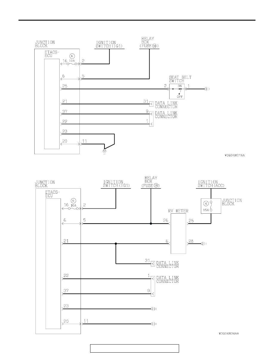
General circuit diagram for seat belt tone alarm function

General circuit diagram for RV meter operating sound function

SYMPTOM PROCEDURES

TSB Revision

SIMPLIFIED WIRING SYSTEM (SWS)

54B-78

INSPECTION PROCEDURE B-1: Tone Alarm: Ignition key reminder tone alarm function does not work 
normally.

NOTE: This troubleshooting procedure requires the 
use of scan tool MB991958 and SWS monitor kit 
MB991862. For details on how to use the SWS mon-
itor, refer to "How to use SWS monitor 

P.54B-10

."

.

CIRCUIT OPERATION
The ETACS-ECU operates the ignition key reminder 
tone alarm function (sounds the tone alarm intermit-
tently), based on input signals from the following 
switches:

• Ignition switch (IG1): OFF

• Key reminder switch: OFF

• Driver’s door switch: ON

The ETACS-ECU operates the ignition key reminder 
tone alarm function (sounds the tone alarm intermit-
tently) if any of the following conditions are satisfied:

• Ignition switch: LOCK position (key inserted)

• Driver’s door: OPEN

.

TECHNICAL DESCRIPTION (COMMENT)
If the function does not work normally, the input cir-
cuit system from the switches or the ETACS-ECU 
may be defective (refer to "CIRCUIT OPERATION").

.

TROUBLESHOOTING HINTS

• The key reminder switch may be defective

• The front door switches may be defective

• The ETACS-ECU may be defective

• The wiring harness or connectors may have 

loose, corroded, or damaged terminals, or termi-
nals pushed back in the connector

DIAGNOSIS

Required Special Tools:

• MB991223: Harness Set

• MB991958: Scan Tool (MUT-III Sub Assembly)

• MB991824: Vehicle Communication Interface (V.C.I.)

• MB991827: MUT-III USB Cable

• MB991911: MUT-III Main Harness B

• MB991813: SWS Monitor Kit

• MB991806: SWS Monitor Cartridge

• MB991812: SWS Monitor Harness (For Column-ECU)

• MB991822: Probe Harness

Ignition Key Reminder Tone Alarm Function

SYMPTOM PROCEDURES

TSB Revision

SIMPLIFIED WIRING SYSTEM (SWS)

54B-79

STEP 1. Use scan tool MB991958 to select "ECU COMM 
CHK" on the SWS monitor display.

Check the ETACS-ECU.

CAUTION

To prevent damage to scan tool MB991958, always turn the 
ignition switch to the "LOCK" (OFF) position before con-
necting or disconnecting scan tool MB991958.
(1) Connect the special tool. Refer to "How to connect SWS 

monito

P.54B-7

(2) Connect SWS monitor kit MB991862 to the data link 

connector (13-pin).

(3) Turn the ignition switch to the "LOCK" (OFF) position.
(4) Operate scan tool MB991958 according to the procedure 

below to display "ECU COMM CHK."

1. Select "SYSTEM SELECT."
2. Select "SWS."
3. Select "SWS MONITOR."
4. Select "ECU COMM CHK."

(5) Scan tool MB991958 should show "OK" on the "ECU 

COMM CHK" menu for the "ETACS ECU" menu.

Q: Is "OK" displayed on the "ETACS ECU" menu?

YES : Go to Step 2.
NO :  Refer to Inspection Procedure A-3 "Communication 

with ETACS-ECU is not possibl

P.54B-42

."

AC309091

MB991911

MB991827

MB991824 

AB

MB991806

MB991862

DATA LINK
CONNECTOR 
(16-PIN)

DATA LINK
CONNECTOR 
(13-PIN)

SYMPTOM PROCEDURES

TSB Revision

SIMPLIFIED WIRING SYSTEM (SWS)

54B-80

STEP 2. Check the input signal by using "FUNCTION 
DIAG." menu of the SWS monitor.

Check the input signals from the following switches: 

• Ignition switch: OFF (key inserted)

• Driver’s door: open

• Front passenger's door: closed

Operate scan tool MB991958 according to the procedure below 
to display "KEY RMND. ALM."

1. Select "SYSTEM SELECT."
2. Select "SWS."
3. Select "SWS MONITOR."
4. Select "FUNCTION DIAG."
5. Select "BUZZER."
6. Select "KEY RMND. ALM."

Check that normal conditions are displayed on the items 
described in the table below.
NOTE: The scan tool display changes when the driver's or the 
front passenger's door is opened. If any of the doors is open, 
the system can not be checked correctly.

Q: Are normal conditions displayed on the "IG SW (IG1)", 

"FRONT DOOR SW" and "BUZZER"?
Normal conditions are displayed for all the items : 

Replace the ETACS-ECU. The ignition key reminder 
tone alarm function should now work normally.

The scan tool does not show the respective normal 
condition for item "IG SW (IG1)." : 
Refer to Inspection 

Procedure O-2 "ETACS-ECU does not receive any 
signal from the ignition switch (IG1) 

P.54B-505

."

The scan tool does not show the respective normal 
condition for item "FRONT DOOR SW." : 
Refer to 

Inspection Procedure O-5 "ETACS-ECU does not 
receive any signal from the driver's or the front 
passenger's door switch 

P.54B-520

."

The scan tool does not show the respective normal 
condition for item "BUZZER." : 
Go to Step 3.

ITEM NO.

ITEM NAME

NORMAL 
CONDITION

ITEM 30

IG SW (IG1)

OFF

ITEM 32

FRONT DOOR SW

ON

ITEM 43

BUZZER

ON

AC309091

MB991911

MB991827

MB991824 

AB

MB991806

MB991862

DATA LINK
CONNECTOR 
(16-PIN)

DATA LINK
CONNECTOR 
(13-PIN)


Content   ..  703  704  705  706   ..