Mitsubishi Montero (2004+). Manual - part 563
VIDEO ENTERTAINMENT SYSTEM (VES)
TSB Revision
CHASSIS ELECTRICAL
54A-221
INSPECTION PROCEDURE 4: Only the image (including sound), which are sent from auxiliary
equipment, is not displayed.
.
CIRCUIT OPERATION
The video controller unit receives image (or sound)
data from an auxiliary equipment, which is connected
to the VTR adapter.
.
TECHNICAL DESCRIPTION (COMMENT)
The circuit between the video controller unit and the
VTR adapter may be defective.
.
TROUBLESHOOTING HINTS
• Malfunction of the VTR adapter
• Malfunction of the video controller unit
• Damaged wiring harness and connectors
.
DIAGNOSIS
Required Special Tool:
• MB991223: Harness Set
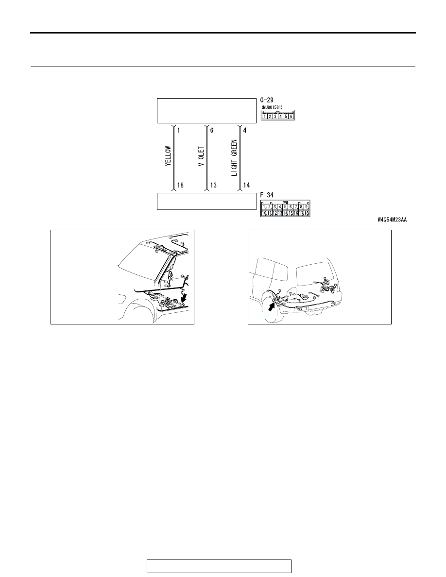
VIDEO CONTROLLER UNIT
VTR ADAPTER
VTR Adapter Circuit
AC309223
AC
CONNECTOR: F-34
AC309248
AC
CONNECTOR: G-29
G-29 (B)