Mitsubishi Montero (2004+). Manual - part 561


  Index      Mitsubishi     Mitsubishi Montero - service repair manual 2004 year


Search            


Content   ..  559  560  561  562   ..


Mitsubishi Montero (2004+). Manual - part 561


VIDEO ENTERTAINMENT SYSTEM (VES)

TSB Revision

CHASSIS ELECTRICAL

54A-213

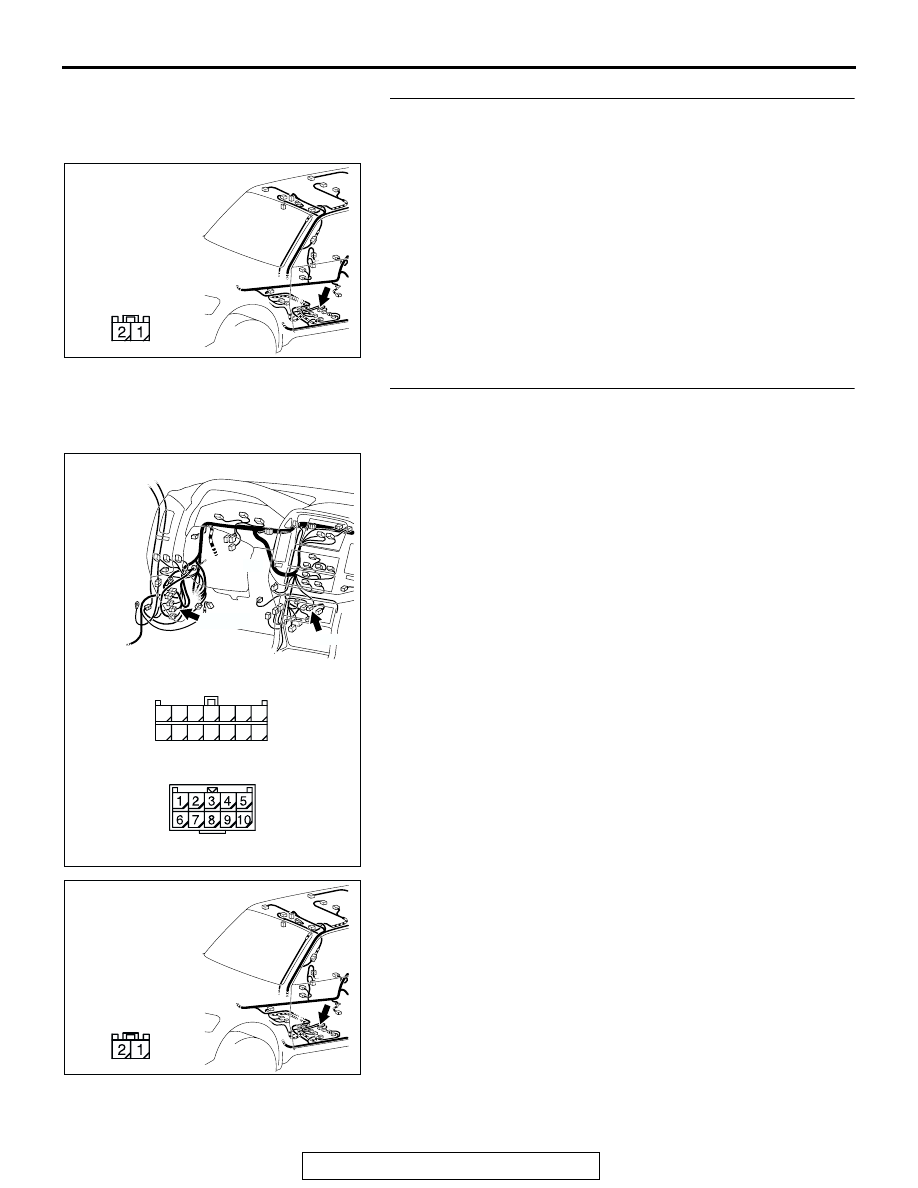
STEP 22. Check the video controller unit connector F-37 
for loose, corroded or damaged terminals, or terminals 
pushed back in the connector.
Q: Is the video controller unit connector F-37 in good 

condition?
YES : 
Go to Step 23.
NO :  Repair or replace the component(s). Refer to GROUP 

00E, Harness Connector Inspection 

P.00E-2

. The 

rear display works normally.

STEP 23. Check the wiring harness between DVD player 
connector D-33 (terminal 3) and video controller unit 
connector F-37 (terminal 2).

AC309223

AE

CONNECTOR: F-37

HARNESS SIDE

AC309208

HARNESS SIDE

D-33

D-139

AF

CONNECTORS: D-33, D-139

D-139

D-33

14

7

1

8

11

12

13

9

10

4

6 5

3 2

AC309223

AE

CONNECTOR: F-37

HARNESS SIDE

VIDEO ENTERTAINMENT SYSTEM (VES)

TSB Revision

CHASSIS ELECTRICAL

54A-214

NOTE: Also check intermediate connector D-139 for loose, cor-
roded, or damaged terminals, or terminals pushed back in the 
connector. If intermediate connector D-139 is damaged, repair 
or replace. Refer to GROUP 00E, Harness Connector Inspec-
tion 

P.00E-2

.

Q: Is the wiring harness between DVD player connector 

D-33 (terminal 3) and video controller unit connector 
F-37 (terminal 2) in good condition?
YES : 
Go to Step 24.
NO :  Repair the wiring harness. The rear display works 

normally.

STEP 24. Check the wiring harness between DVD player 
connector D-33 (terminal 12) and video controller unit 
connector F-34 (terminal 15).
NOTE: Also check intermediate connector D-139 for loose, cor-
roded, or damaged terminals, or terminals pushed back in the 
connector. If intermediate connector D-139 is damaged, repair 
or replace. Refer to GROUP 00E, Harness Connector Inspec-
tion 

P.00E-2

.

Q: Is the wiring harness between DVD player connector 

D-33 (terminal 12) and video controller unit connector 
F-34 (terminal 15) in good condition?
YES : 
Go to Step 25.
NO :  Repair the wiring harness. The rear display works 

normally.

STEP 25. Check the rear display connector F-32 for loose, 
corroded or damaged terminals, or terminals pushed back 
in the connector.

Q: Is the rear display connector F-32 in good condition?

YES : Go to Step 26.
NO :  Repair or replace the component(s). Refer to GROUP 

00E, Harness Connector Inspection 

P.00E-2

. The 

rear display works normally.

AC309223

AF

CONNECTOR: F-32

HARNESS SIDE

F-32 (B)

VIDEO ENTERTAINMENT SYSTEM (VES)

TSB Revision

CHASSIS ELECTRICAL

54A-215

STEP 26. Check the wiring harness between video 
controller unit connector F-35 (terminal 25, 23, 21 and 30) 
and rear display connector F-32 (terminal 1, 16, 15 and 7).

NOTE: Also check intermediate connector D-34 for loose, cor-
roded, or damaged terminals, or terminals pushed back in the 
connector. If intermediate connector D-34 is damaged, repair or 
replace. Refer to GROUP 00E, Harness Connector Inspection 

P.00E-2

.

Q: Is the wiring harness between video controller unit 

connector F-35 (terminal 25, 23, 21 and 30) and rear 
display connector F-32 (terminal 1, 16, 15 and 7) in good 
condition?
YES : 
Go to Step 27.
NO :  Repair the wiring harness. The rear display works 

normally.

STEP 27. Substitute the DVD player, and retest the system.

Confirm that the rear display shows image after the DVD player 
is substituted.
Q: Is the check result normal?

YES : Replace the DVD player.
NO :  Go to Step 28.

AC309224

AB

CONNECTOR: F-32, F-35

HARNESS SIDE

F-32 (B)

F-32

F-35

HARNESS SIDE

F-35

AC309207

AD

CONNECTOR: D-34

HARNESS SIDE

4

11

1

8 9

2

10

3

5

1213

6

14

7

VIDEO ENTERTAINMENT SYSTEM (VES)

TSB Revision

CHASSIS ELECTRICAL

54A-216

STEP 28. Substitute the video controller unit, and retest 
the system.

Confirm that the rear display shows image after the video con-
troller unit is substituted.
Q: Is the check result normal?

YES : Replace the video controller unit.
NO :  Go to Step 29.

STEP 29. Substitute the rear display, and retest the 
system.
Confirm that the rear display shows image after it is substituted.
Q: Is the check result normal?

YES : Replace the rear display.
NO :  Go to Step 1.

INSPECTION PROCEDURE 2: The remote control does not function.

.

CIRCUIT OPERATION
 Refer to 

P.54A-196

.

.

TECHNICAL DESCRIPTION (COMMENT)
The ground circuit, the battery circuit, the ignition 
switch (ACC) circuit is suspected to be open or 
defective.

.

TROUBLESHOOTING HINTS

• Malfunction of the remote controller

• Malfunction of the video controller unit

• Malfunction of the rear display

• Damaged wiring harness and connectors

.

DIAGNOSIS 

Required Special Tool:

• MB991223: Harness Set

STEP 1. Check the remote controller batteries.

Confirm that the remote control batteries are normal.
Q: Is the check result normal?

YES : Go to Step 2.
NO :  Replace the remote controller batteries.


Content   ..  559  560  561  562   ..