Mitsubishi Montero (2004+). Manual - part 564
 

  Index      Mitsubishi     Mitsubishi Montero - service repair manual 2004 year


Search            


Content   ..  562  563  564  565   ..


Mitsubishi Montero (2004+). Manual - part 564


VIDEO ENTERTAINMENT SYSTEM (VES)

TSB Revision

CHASSIS ELECTRICAL

54A-225

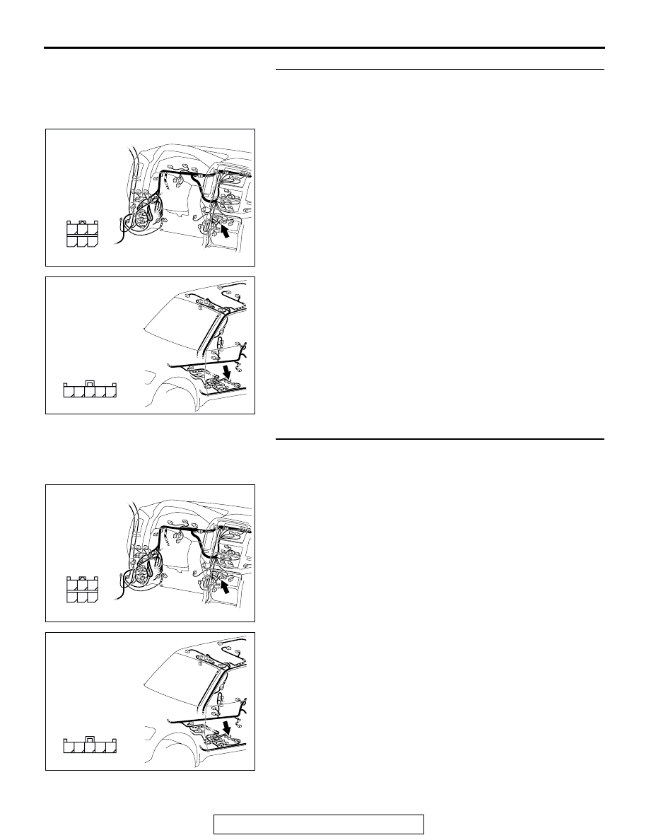
STEP 2. Check the video controller unit connector F-36 
and DVD player connector D-35 for loose, corroded or 
damaged terminals, or terminals pushed back in the 
connector.
Q: Is the video controller unit connector F-36 and DVD 

player connector D-35 in good condition?
YES : 
Go to Step 3.
NO :  Repair or replace the component(s). Refer to GROUP 

00E, Harness Connector Inspection 

P.00E-2

. The 

DVD sound comes out normally.

STEP 3. Check the wiring harness between video 
controller unit connector F-36 (terminal 13, 12) and DVD 
player connector D-35 (terminal 24, 21).

Q: Is the wiring harness between video controller unit 

connector F-36 (terminal 13, 12) and DVD player 
connector D-35 (terminal 24, 21) in good condition?
YES : 
Go to Step 4.
NO :  Repair the wiring harness. The DVD sound comes out 

normally.

AC309207

AH

CONNECTOR: D-35

HARNESS SIDE

21

22

23

24

25

26

AC309223

HARNESS SIDE

AJ

CONNECTOR: F-36

11

12

13

14

15

AC309207

AH

CONNECTOR: D-35

HARNESS SIDE

21

22

23

24

25

26

AC309223

HARNESS SIDE

AJ

CONNECTOR: F-36

11

12

13

14

15

VIDEO ENTERTAINMENT SYSTEM (VES)

TSB Revision

CHASSIS ELECTRICAL

54A-226

STEP 4. Check the video controller unit connector F-35 
and rear display connector D-34 for loose, corroded or 
damaged terminals, or terminals pushed back in the 
connector.

Q: Is the video controller unit connector F-35 and rear 

display connector D-34 in good condition?
YES : 
Go to Step 5.
NO :  Repair or replace the component(s). Refer to GROUP 

00E, Harness Connector Inspection 

P.00E-2

. The 

DVD sound comes out normally.

STEP 5. Check the wiring harness between video 
controller unit connector F-35 (terminal 28, 27) and rear 
display connector F-32 (terminal 5, 4).

Q: Is the wiring harness between video controller unit 

connector F-35 (terminal 28, 27) and rear display 
connector F-32 (terminal 5, 4) in good condition?
YES : 
Go to Step 6.
NO :  Repair the wiring harness. The DVD sound comes out 

normally.

AC309207

AD

CONNECTOR: D-34

HARNESS SIDE

4

11

1

8 9

2

10

3

5

1213

6

14

7

AC309223

AD

CONNECTOR: F-35

HARNESS SIDE

21

22

23

24

25

26

AC309224

AB

CONNECTOR: F-32, F-35

HARNESS SIDE

F-32 (B)

F-32

F-35

HARNESS SIDE

F-35

VIDEO ENTERTAINMENT SYSTEM (VES)

TSB Revision

CHASSIS ELECTRICAL

54A-227

STEP 6. Substitute the DVD player, and retest the system.

Confirm that sound comes out of the DVD player after it is sub-
stituted.
Q: Is the check result normal?

YES : Replace the DVD player.
NO :  Go to Step 7.

STEP 7. Substitute the rear display, and retest the system.

Confirm that sound comes out of the DVD player after the rear 
display is substituted.
Q: Is the check result normal?

YES : Replace the rear display.
NO :  Go to Step 8.

STEP 8. Substitute the video controller unit, and retest the 
system.

Confirm that sound comes out of the DVD player after the video 
controller unit is substituted.
Q: Is the check result normal?

YES : Replace the video controller unit.
NO :  Go to Step 1.

CHECK AT MAIN UNIT TERMINAL VOLTAGE

M1546200400034

DVD PLAYER

AC309213AB

D-35

D-33

VIDEO ENTERTAINMENT SYSTEM (VES)

TSB Revision

CHASSIS ELECTRICAL

54A-228

<CONNECTOR D-33>

<CONNECTOR D-35>

TERMINAL 
NO.

INPUT/ 
OUTPUT

SIGNAL 
SYMBOL

TERMINAL 
VOLTAGE (V)

HARNESS DISCREPANCY

FAILURE 
SYMPTOM DUE 
TO HARNESS 
DISCREPANCY

− 2

3

Output

DVD-VIDEO-
OUT

− 1 Vp-p 

(AC)

Open circuit

Short circuit

DVD image is not 
displayed.

4

5

REMO-SIG-G
ND

6

Input

ACC

Hi: Battery 
positive 
voltage 
(AC)Lo: 0 

− 1

Open circuit

The DVD player 
does not work.

Short circuit

ACC system fuse 
is melted.

7

GND

Open circuit

The DVD player 
does not work.

− 9

10

DVD-VIDEO-
GND

11

12

Input

REMO-SIG-I
N

− 5 Vp-p 

(DC)

Open circuit

Short circuit

The remote control 
does not function.

13

Output

DVD-ON

0.9 

− 5 Vp-p 

(DC)

Open circuit

The DVD player 
does not work.

Short circuit

The DVD player is 
always working.

14

Input

+B

Battery 
positive 
voltage

Short circuit

Multi-purpose fuse 
is melted.

TERMINAL 
NO.

INPUT/ 
OUTPUT

SIGNAL 
SYMBOL

TERMINAL 
VOLTAGE (V)

HARNESS DISCREPANCY

FAILURE 
SYMPTOM DUE 
TO HARNESS 
DISCREPANCY

21

Output

DVD-AUDIO-
R-OUT

− 1.4 Vp-p 

(AC)

Open circuit

Short circuit

Sound does not 
come out of the 
right headphone.

22 

− 23

24

Output

DVD-AUDIO-
L-OUT

− 1.4 Vp-p 

(AC)

Open circuit

Short circuit

Sound does not 
come out of the left 
headphone.

25

AUDIO-SIG-
GND

26


Content   ..  562  563  564  565   ..