Mitsubishi Montero (2004+). Manual - part 523


  Index      Mitsubishi     Mitsubishi Montero - service repair manual 2004 year


Search            


Content   ..  521  522  523  524   ..


Mitsubishi Montero (2004+). Manual - part 523


COMBINATION METER ASSEMBLY AND VEHICLE SPEED SENSOR

TSB Revision

CHASSIS ELECTRICAL

54A-61

STEP 2. Check the engine coolant temperature gauge unit.
Check to see that the engine coolant temperature gauge unit 
operates normally. Refer to 

P.54A-75

.

Q:  Is the engine coolant temperature gauge unit normal?

YES : Go to Step 3.
NO :  Replace the engine coolant gauge unit. The engine 

coolant gauge should work normally.

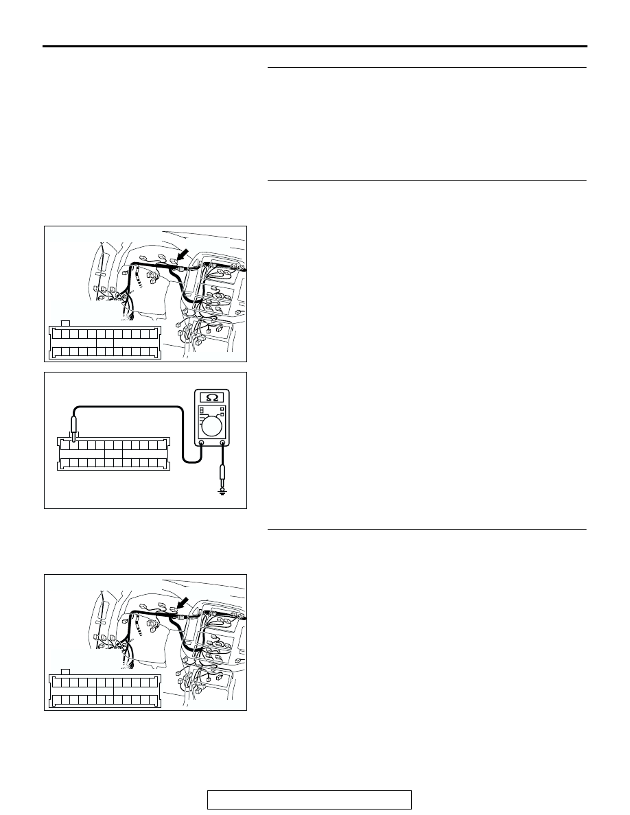
STEP 3. Measure at combination meter connector D-32 in 
order to the ground circuit to the engine coolant 
temperature gauge.

(1) Disconnect combination meter connector D-32 and 

measure at the wiring harness side.

(2) Measure the resistance value between terminal 11 and 

ground.

• The resistance should equal 2 ohms or less.

Q: Is the measured resistance 2 ohms or less?

YES : Go to Step 6.
NO :  Go to Step 4.

STEP 4. Check combination meter connector D-32 for 
loose, corroded or damaged terminals, or terminals 
pushed back in the connector.

Q: Is combination meter connector D-32 in good 

condition?
YES : 
Go to Step 5.
NO :  Repair or replace the damaged component(s). Refer 

to GROUP 00E, Harness Connector Inspection 

P.00E-2

The fuel gauge should work normally.

AC204170

CONNECTOR : D-32

CU

HARNESS SIDE

D-32(GR)

D-32(GR)

3

4

16

17

1

2

14

15

5

7 6

19

13

8

9

21

22

20

18

23

10

11

24

25

12

AC204738 EF

HARNESS SIDE: D-32

3

4

16

17

1

2

14

15

5

7 6

19

13

8

9

21

22

20

18

23

10

11

24

25

12

AC204170

CONNECTOR : D-32

CU

HARNESS SIDE

D-32(GR)

D-32(GR)

3

4

16

17

1

2

14

15

5

7 6

19

13

8

9

21

22

20

18

23

10

11

24

25

12

COMBINATION METER ASSEMBLY AND VEHICLE SPEED SENSOR

TSB Revision

CHASSIS ELECTRICAL

54A-62

STEP 5. Check the wiring harness between combination 
meter connector D-32 (terminal 11) and ground.

Q: Is the wiring harness between combination meter 

connector D-32 (terminal 11) and ground in good 
condition?
YES : 
There is no action to be taken.
NO :  Repair the wiring harness. The fuel gauge should 

work normally.

STEP 6. Check engine coolant temperature gauge unit 
connector B-38 and combination meter connector D-03 for 
loose, corroded or damaged terminals, or terminals 
pushed back in the connector.

Q: Are engine coolant temperature gauge unit connector 

B-38 and combination meter connector D-03 in good 
condition?
YES : 
Go to Step 7.
NO :  Repair or replace the damaged component(s). Refer 

to GROUP 00E, Harness Connector Inspection 

P.00E-2

The engine coolant gauge should work 

normally.

AC204170

CONNECTOR : D-32

CU

HARNESS SIDE

D-32(GR)

D-32(GR)

3

4

16

17

1

2

14

15

5

7 6

19

13

8

9

21

22

20

18

23

10

11

24

25

12

AC204168

CONNECTOR : B-38

B-38(B)

B-38(B)

AD

1

HARNESS
SIDE

AC204170

CONNECTOR : D-03

AC

D-03(GR)

HARNESS 
SIDE

51

52

61 60

53

54

56

57

55

63

66 65 64

59

62

58

67

D-03(GR)

COMBINATION METER ASSEMBLY AND VEHICLE SPEED SENSOR

TSB Revision

CHASSIS ELECTRICAL

54A-63

STEP 7. Check the wiring harness between engine coolant 
temperature gauge unit connector B-38 (terminal 1) and 
combination meter connector D-03 (terminal 64).

NOTE: Also check intermediate connector E-111. If intermedi-
ate connector E-111 is damaged, repair or replace the connec-
tor as described in GROUP 00E, Harness Connector 
Inspection 

P.00E-2

.

Q: Is the wiring harness between engine coolant 

temperature gauge unit connector B-38 (terminal 1) and 
combination meter connector D-03 (terminal 64) in good 
condition?
YES : 
Repair or replace the combination meter. The engine 

coolant gauge should work normally.

NO :  Repair the wiring harness. The engine coolant gauge 

should work normally.

AC204168

CONNECTOR : B-38

B-38(B)

B-38(B)

AD

1

HARNESS
SIDE

AC204170

CONNECTOR : D-03

AC

D-03(GR)

HARNESS 
SIDE

51

52

61 60

53

54

56

57

55

63

66 65 64

59

62

58

67

D-03(GR)

AC204176

CONNECTOR : E-111

BF

15

4

14

37

36

26 27

12

11

35

34

23 24

3

13

25

9

2

8

32

20 21

6

5

17

29

30

18

1

7

19

31

10

22

33

16

28

38

COMBINATION METER ASSEMBLY AND VEHICLE SPEED SENSOR

TSB Revision

CHASSIS ELECTRICAL

54A-64

INSPECTION PROCEDURE 6: Combination Meter does not Work.

.

CIRCUIT OPERATION
The combination meter is powered by the ignition 
switch (IG1) and the battery.

.

TECHNICAL DESCRIPTION (COMMENT)
The cause is thought to be malfunction of the power, 
ground circuitry of the combination meter.

.

COMBINATION
METER

FUEL
GAUGE

CPU

TACHO
METER

SPEED
METER

TEMP
GAUGE

IGNITION
SWITCH (IG1)

FUSIBLE
LINK

1

JUNCTION
BLOCK

RELAY
BOX

Combination Meter Power Supply Circuit

AC204170

CONNECTORS : D-03, D-28, D-32

DD

D-03(GR)

D-28

D-32(GR)

AC204173

CONNECTORS : D-208, D-210, D-217, D-221

BI

D-208

D-210

D-217

D-221


Content   ..  521  522  523  524   ..