Mitsubishi Montero (2004+). Manual - part 518


  Index      Mitsubishi     Mitsubishi Montero - service repair manual 2004 year


Search            


Content   ..  516  517  518  519   ..


Mitsubishi Montero (2004+). Manual - part 518


COMBINATION METER ASSEMBLY AND VEHICLE SPEED SENSOR

TSB Revision

CHASSIS ELECTRICAL

54A-41

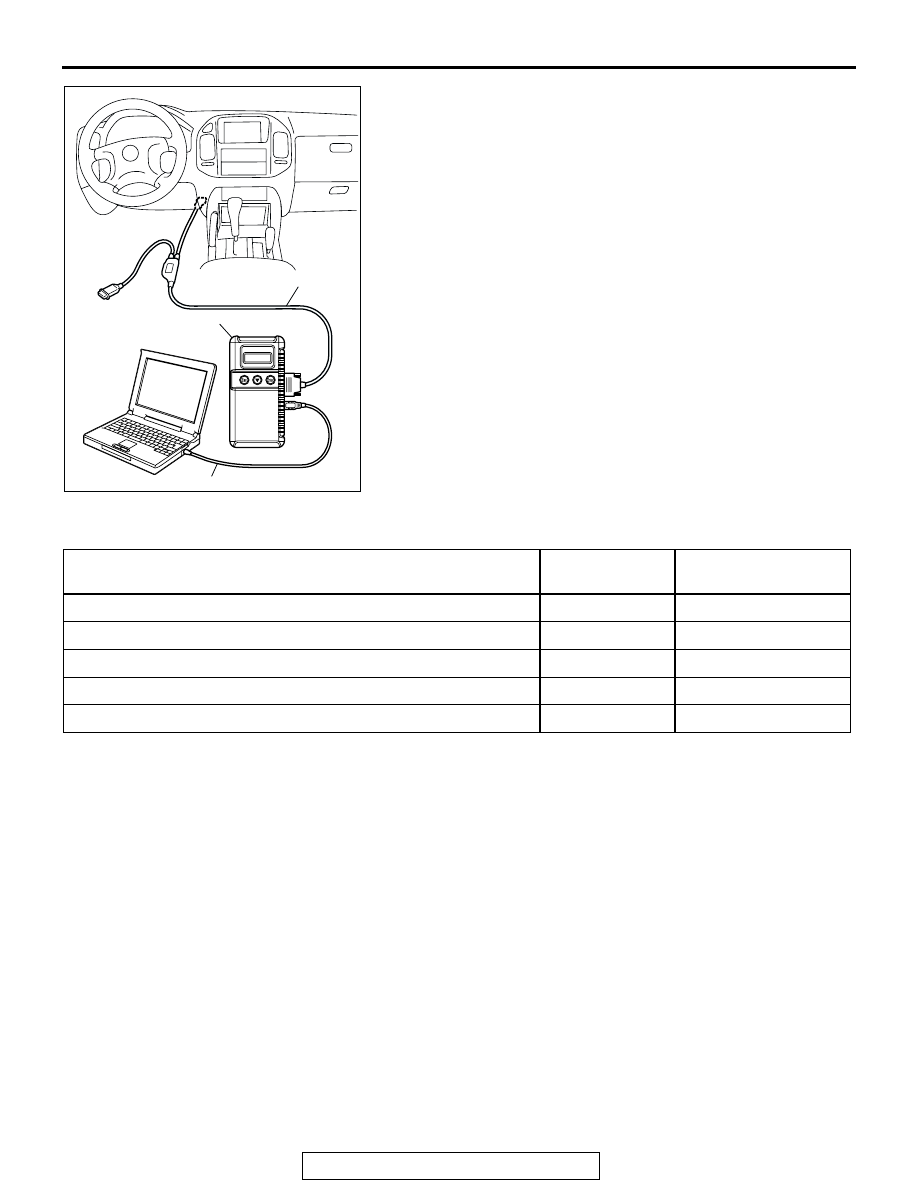
1. Ensure that the ignition switch is at the "LOCK" (OFF) 

position.

2. Start up the personal computer.
3. Connect special tool MB991827 to special tool MB991824 

and the personal computer.

4. Connect special tool MB991911 to special tool MB991824.
5. Connect special tool MB991911 to the data link connector.
6. Turn the power switch of special tool MB991824 to the "ON" 

position.
NOTE: When special tool MB991824 is energized, special 
tool MB991824 indicator light will be illuminated in a green 
color.

7. Start the MUT-III system on the personal computer.

NOTE: Disconnecting scan tool MB991958 is the reverse of 
the connecting sequence, making sure that the ignition 
switch is at the "LOCK" (OFF) position.

SYMPTOM CHART

M1543007200771

AC306409AF

MB991911

MB991824

MB991827

SYMPTOM

INSPECTION 
PROCEDURE

REFERENCE PAGE

Speedometer does not work.

1

P.54A-42

Tachometer does not work.

2

P.54A-47

Fuel gauge does not work.

3

P.54A-52

Engine coolant temperature gauge does not work.

4

P.54A-59

Combination meter does not work.

5

P.54A-64

COMBINATION METER ASSEMBLY AND VEHICLE SPEED SENSOR

TSB Revision

CHASSIS ELECTRICAL

54A-42

SYMPTOM PROCEDURES

INSPECTION PROCEDURE 1: Speedometer does not Work.

COMBINATION
METER

CPU

SPEED
METER

VEHICLE SPEED
SENSOR

JOINT 
CONNECTOR (4)

Speedometer Circuit

AC204395

CONNECTOR : C-08

AJ

C-08(B)

AC204170

CONNECTOR : D-03

DC

D-03(GR)

COMBINATION METER ASSEMBLY AND VEHICLE SPEED SENSOR

TSB Revision

CHASSIS ELECTRICAL

54A-43

.

CIRCUIT OPERATION

• The ignition switch (IG1) circuit is the power sup-

ply for the speedometer and vehicle speed sen-
sor.

• The vehicle speed sensor is installed on the 

transmission. Four pulses are generated with one 
turn of the vehicle speed sensor shaft. These 
pulse signals are sent into the PCM and sent into 
the speedometer. The speedometer calculates 
the pulse signals, and operates the indicator. At 
the same time, the travel distance is calculated.

.

TECHNICAL DESCRIPTION (COMMENT)
The cause may be a faulty vehicle speed sensor cir-
cuit system or a faulty speedometer. The vehicle 
speed sensor is also used by the powertrain control 
module (PCM), the auto-cruise control-ECU.

.

TROUBLESHOOTING HINTS

• Malfunction of the vehicle speed sensor

• Malfunction of the combination meter (printed-cir-

cuit board or speedometer and tachometer)

• Malfunction of the PCM

• Malfunction of the auto-cruise control-ECU

• The wiring harness or connectors may have 

loose, corroded, or damaged terminals, or termi-
nals pushed back in the connector

DIAGNOSIS 

Required Special Tools:

• MB991223: Harness Set

• MB991958: Scan Tool (MUT-III Sub Assembly)

• MB991824: Vehicle Communication Interface (V.C.I.)

• MB991827: MUT-III USB Cable

• MB991911: MUT-III Main Harness B

STEP 1. Check the speedometer by observing the other 
meters.

Check to see that the tachometer, fuel gauge and water ther-
mometer are operating normally.
Q:  Do all other meters operate?

 YES <other meters all operate> : Go to Step 2.
 NO <one of the meters do not operate> : Refer to 

INSPECTION PROCEDURE 5 

P.54A-64

.

AC204171

CONNECTOR : D-116

AI

AC204176

CONNECTORS : E-111, E-114

E-111

AL

E-114

COMBINATION METER ASSEMBLY AND VEHICLE SPEED SENSOR

TSB Revision

CHASSIS ELECTRICAL

54A-44

STEP 2. Using scan tool MB991958, read the MFI system 
diagnostic trouble code.

CAUTION

To prevent damage to scan tool MB991958 always turn the 
ignition switch to "LOCK" (OFF) position before connect-
ing or disconnecting scan tool.

1. Connect scan tool MB991958 to the data link connector. 

2. Turn the ignition switch "ON" position.
3. Check the MFI system diagnostic trouble code.

Q: Are MFI system-related DTC(s) sets to the MFI system?

YES : Refer to GROUP 13A, Multiport Fuel Injection (MFI) 

Diagnosis 

P.13A-26

.

NO :  Go to Step 3.

AC306409AF

MB991911

MB991824

MB991827


Content   ..  516  517  518  519   ..