Mitsubishi Montero (2004+). Manual - part 517


  Index      Mitsubishi     Mitsubishi Montero - service repair manual 2004 year


Search            


Content   ..  515  516  517  518   ..


Mitsubishi Montero (2004+). Manual - part 517


IGNITION SWITCH

TSB Revision

CHASSIS ELECTRICAL

54A-37

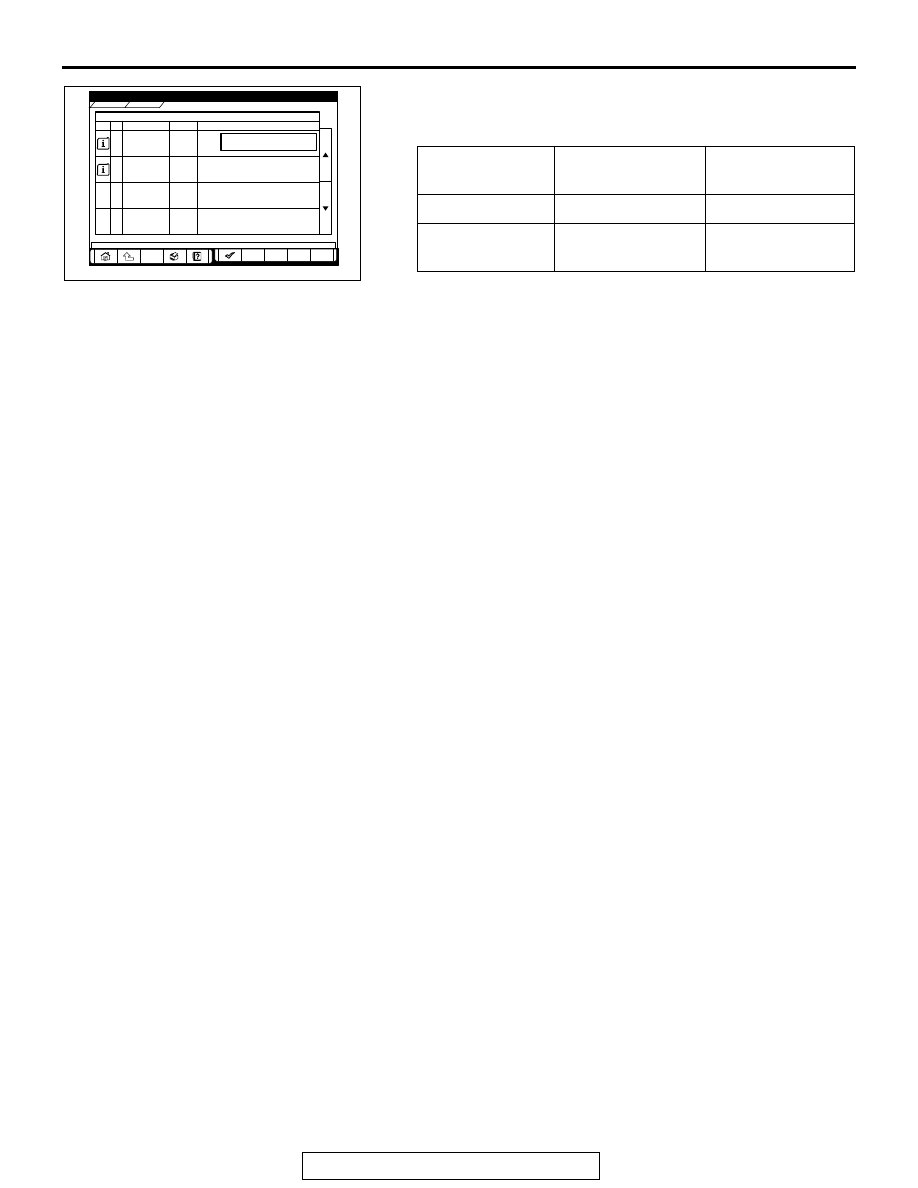
7. The multi-center display shows whether the ignition key, 

which has been inserted in the switch, can be rewritten and 
how many ignition keys have ever been registered.

TP LOCK 
CHECK

IGNITION KEY:

JUDGMENT OF 
IGNITION KEY

UNLOCK

Can be overwritten Correct

LOCK

Can not be 
overwritten

Incorrect

AC209776

POWERTRAIN

IMMOBILIZER

Data List Reference T

Data List Reference Table

able

Info.

Info. No.

No.

01

REGD.KEY

3

TP LOCK CHECK

UNLOCK

02

Name

Name

Value

alue

Graph

Graph

Data List

Data List

AB

IGNITION SWITCH

TSB Revision

CHASSIS ELECTRICAL

54A-38

IGNITION SWITCH

REMOVAL AND INSTALLATION

M1543002100519

WARNING

Before removal of the air bag module and clock spring, refer to GROUP 52B, SRS Service 
Precautions (

P.52B-18

) and Air Bag Module and Clock Spring (

P.52B-217

).

When removing and installing the steering wheel, do not let it bump against the air bag 
module.

Post-installation operation
• Register the ignition key(s) when the immobilizer-ECU is replaced (Refer to 

P.54A-29

).

ACX01372

1

2

3

4

5

6

7

8

ACX01568

AD

DIAGNOSIS CONNECTOR

9

AD

IGNITION SWITCH REMOVAL 
STEPS

1. STEERING WHEEL (REFER TO 

GROUP 37, STEERING WHEEL AND 
SHAFT 

P.37A-22

).

2. INSTRUMENT UNDER COVER
3. COLUMN COVER LOWER
4. COLUMN COVER UPPER
5. COLUMN SWITCH

<<A>>

6. STEERING LOCK CYLINDER

7. IGNITION SWITCH
8. KEY REMINDER SWITCH

IMMOBILIZER-ECU REMOVAL 
STEPS

• LOWER CENTER PANEL <LH> 

(REFER TO GROUP52A, FLOOR 
CONSOLE ASSEMBLY 

P.52A-7

).

9. IMMOBILIZER-ECU

IGNITION SWITCH REMOVAL 
STEPS (Continued)

IGNITION SWITCH

TSB Revision

CHASSIS ELECTRICAL

54A-39

REMOVAL SERVICE POINT

.

<<A>> STEERING LOCK CYLINDER REMOVAL
1. Insert the key in the steering lock cylinder and turn it to the 

"ACC" position.

2. Using a small Phillips head screwdriver, pull the steering 

lock cylinder toward you.

INSPECTION

M1543019502708

IGNITION SWITCH LESS CONINUITY CHECK

Disconnect ignition switch connector without removing the igni-
tion switch and steering lock cylinder. Then check the continu-
ity.

KEY REMINDER SWITCH CHECK

Disconnect key reminder switch connector without removing 
the ignition switch and steering lock cylinder. Then check the 
continuity.

IGNITION KEY RING ANTENNA CHECK

Check for continuity between the key reminder switch connec-
tor terminal 3 and terminal 7.

Standard value: 2 ohms or less

ACX01628AB

LOCK PIN

SWITCH 
POSITION

TESTER CONNECTION SPECIFIED 

CONNECTION

"LOCK" (OFF) 1 

− 2, 1 − 3, 1 − 4, 1 − 5, 

− 6, 2 − 4, 2 − 5, 2 − 6, 

− 5, 4 − 6

Open circuit

"ACC"

− 6

Less than 2 ohms

"ON"

− 2, 1 − 4, 1 − 6, 2 − 4, 

− 6, 4 − 6

Less than 2 ohms

"START"

− 2, 1 − 4, 1 − 5, 2 − 4, 

− 5, 4 − 5

Less than 2 ohms

ACX00769AB

STATUS OF 
IGNITION KEY

TESTER 
CONNECTION

SPECIFIED 
CONNECTION

Removed

− 6

Less than 2 ohms

Inserted

− 6

Open circuit

ACX00770 AB

COMBINATION METER ASSEMBLY AND VEHICLE SPEED SENSOR

TSB Revision

CHASSIS ELECTRICAL

54A-40

COMBINATION METER ASSEMBLY AND 

VEHICLE SPEED SENSOR

COMBINATION METERS ASSEMBLY AND VEHICLE SPEED SENSOR 
DIAGNOSIS

INTRODUCTION TO COMBINATION METER DIAGNOSIS

M1543009900992

All vehicles are equipped with an electrical speedom-
eter, tachometer, fuel and coolant temperature 
gauges. The individual gauges are not replaceable. If 
the gauges do not function correctly, there is most 
likely a fault in the electrical system. All inputs, pow-
ers and grounds must be confirmed as correct before 
the combination meter can be condemned.

TROUBLESHOOTING STRATEGY

M1543006900528

Use these steps to plan your diagnostic strategy. Fol-
low through with each step to ensure that you have 
exhausted all possible methods of finding a combina-
tion meter fault.
1. Gather information from the customer.

2. Verify that the condition described by the 

customer exists.

3. Find and repair the malfunction by following the 

symptom chart.

4. Verify that the malfunction has been eliminated.

DIAGNOSIS FUNCTION

M1543007000517

HOW TO CONNECT SCAN TOOL (MUT-III)

Required Special Tools:

• MB991958: Scan Tool (MUT-III Sub Assembly)

• MB991824: Vehicle Communication Interface (V.C.I.)

• MB991827: MUT-III USB Cable

• MB991911: MUT-III Main Harness B

CAUTION

To prevent damage to scan tool MB991958, always turn the 
ignition switch to the "LOCK" (OFF) position before con-
necting or disconnecting scan tool MB991958.


Content   ..  515  516  517  518   ..