Mitsubishi Montero (2004+). Manual - part 511


  Index      Mitsubishi     Mitsubishi Montero - service repair manual 2004 year


Search            


Content   ..  509  510  511  512   ..


Mitsubishi Montero (2004+). Manual - part 511


IGNITION SWITCH

TSB Revision

CHASSIS ELECTRICAL

54A-13

• MB991824: Vehicle Communication Interface (V.C.I.)

• MUT-III USB Cable

• MB991911: MUT-III Main Harness B

STEP 1. Check for presence of other key near the key in 
the ignition.
Q: Is there any other key near the key in the ignition?

YES : Move the other key well away from key being used. 

Retest the system.

NO :  Go to Step 2.

STEP 2. Check that the engine start using the spare 
ignition key which encrypted code has been registered.
Q: Does the engine start using the spare ignition key for 

which the encrypted code has been registered?
YES : 
replace the ignition key that does not work. Then 

register the password (secret code) and encrypted 
code 

P.00E-2

. Retest the system.

NO :  Go to Step 3.

STEP 3. Check that DTC is set, DTC 11 or 12?
Q: Which DTC is set, DTC 11 or 12?

DTC12 is set : Refer to DTC 12 

P.54A-15

.

DTC11 is set : Go to Step 4.

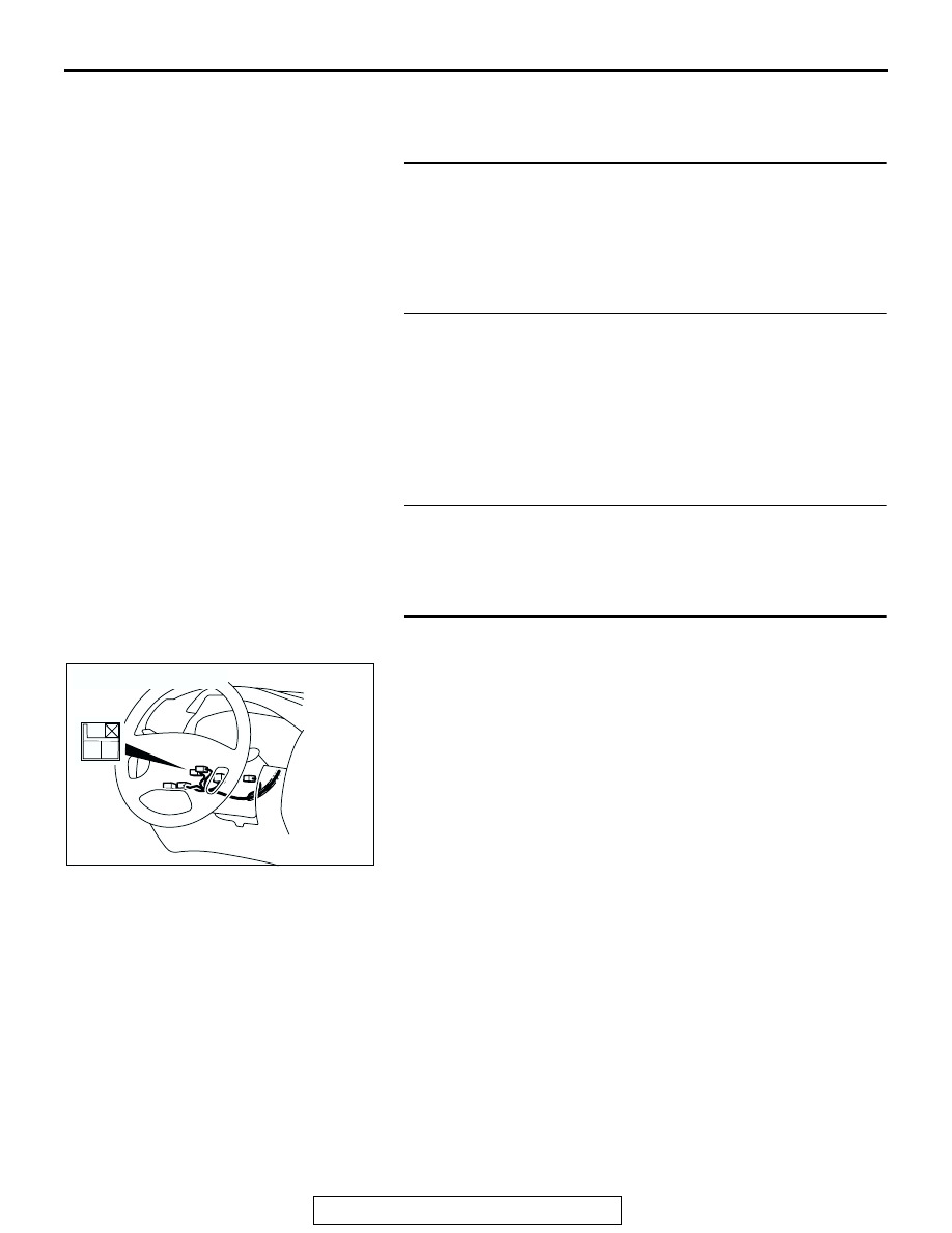
STEP 4. Check the ignition key ring antenna by 
backprobing.

Do not disconnect the ignition key ring antenna connector 
D-201 and check the resistance on the harness side connector 
between terminal number 1 and terminal number 2 by back-
probing.
Q: Is the resistance less than 2 ohms?

YES : Go to Step 5.
NO :  Replace the ignition key ring antenna. Retest the 

system.

ACX01679AC

CONNECTOR: D - 201

1 2

IGNITION SWITCH

TSB Revision

CHASSIS ELECTRICAL

54A-14

STEP 5. Check immobilizer-ECU connector D-121 and 
ignition key ring antenna connector D-201 for loose, 
corroded or damaged terminals, or terminals pushed back 
in the connector.

Q: Are immobilizer-ECU connector D-121 and ignition key 

ring antenna connector D-201 in good condition?
YES : 
Go to Step 6.
NO :  Repair or replace them. Refer to GROUP 00E, 

Harness Connector Inspection 

P.00E-2

. Retest the 

system.

STEP 6. Check the harness wires between 
immobilizer-ECU connector D-121 (terminal 10, 11) and 
ignition key ring antenna connector D-201 (terminal 2, 1).

Q: Are the harness wires between immobilizer-ECU 

connector D-121 (terminal 10, 11) and ignition key ring 
antenna connector D-201 (terminal 2, 1) in good 
condition?
YES : 
replace the immobilizer-ECU. Then register the 

password (secret code) and encrypted code 

P.54A-29

. Retest the system.

NO :  Repair them. Retest the system.

AC204170

CONNECTOR : D-121

CV

HARNESS SIDE

2

3

8 7

9

10

1
6

5

12

4

11

AC204172

CONNECTOR : D-201

AI

2

1

HARNESS SIDE

AC204170

CONNECTOR : D-121

CV

HARNESS SIDE

2

3

8 7

9

10

1
6

5

12

4

11

AC204172

CONNECTOR : D-201

AI

2

1

HARNESS SIDE

IGNITION SWITCH

TSB Revision

CHASSIS ELECTRICAL

54A-15

DTC12: Encrypted Codes are Not the Same or Not Registered

.

DTC SET CONDITION
The encrypted code sent by the transponder is not the same 
encrypted code which is registered in the immobilizer-ECU.
NOTE: DTC 12 is always output together with MFI system DTC 
P1610.

.

TROUBLESHOOTING HINTS

• The encrypted code in the ignition key has not been prop-

erly registered 

• Malfunction of immobilizer-ECU

.

DIAGNOSIS
Was the encrypted code registered?

YES : Replace the immobilizer and then re-register the 

encrypted code (Refer to 

P.54A-29

.)

NO :  Register the encrypted code (Refer to 

P.54A-29

.)

SYMPTOM CHART

M1543007201172

SYMPTOMS

INSPECTION 
PROCEDURE NO.

REFERENCE PAGE

Communication with scan tool MB991958 is impossible.

1

P.54A-16

The ignition key cannot be registered.

2

P.54A-24

Engine cranks, but does not start.

3

P.54A-25

IGNITION SWITCH

TSB Revision

CHASSIS ELECTRICAL

54A-16

SYMPTOM PROCEDURES

INSPECTION PROCEDURE 1: Communication with Scan Tool MB991958 is Impossible.

MFI RELAY

POWER
SUPPLY

POWERTRAIN
CONTROL
MODULE

IMMOBILIZER-
ECU

JOINT 
CONNECTOR (4)

JOINT 
CONNECTOR (8)

Immobilizer-ECU Power Supply, Ground and Powertrain Control Module 
                                      Communication Line Circuit

AC204745

CONNECTOR : B-22X

AC

AC204170

CONNECTORS : D-30, D-121

DO

D-30

D-121


Content   ..  509  510  511  512   ..