Mitsubishi Montero (2004+). Manual - part 510


  Index      Mitsubishi     Mitsubishi Montero - service repair manual 2004 year


Search            


Content   ..  508  509  510  511   ..


Mitsubishi Montero (2004+). Manual - part 510


IGNITION SWITCH

TSB Revision

CHASSIS ELECTRICAL

54A-9

6. If there is an immobilizer system DTC, record the 

DTC, then erase it from the memory using scan 
tool MB991958.

7. Recreate the immobilizer system DTC set 

conditions to see if the same immobilizer system 
DTC will resets.

(1) If the same immobilize system DTC resets, 

perform the appropriate diagnostic procedure. 
Refer to Diagnostic Trouble Code Chart 

P.54A-11

.

(2) If the same immobilizer system DTC does not 

reset, the malfunction is intermittent. Refer to 
GROUP 00, How to Use 
Troubleshooting/inspection Service Points 

− 

How to Cope with Intermittent   Malfunctions 

P.00-6

.

IMMOBILIZER SYSTEM TROUBLE CODE 
DIAGNOSIS

M1543007000476

Retrieving and Erasing Immobilizer System 
Diagnostic Trouble Codes

Required Special Tools:

• MB991958: Scan Tool (MUT-III Sub Assembly)

• MB991824: Vehicle Communication Interface (V.C.I.)

• MB991827: MUT-III USB Cable

• MB991911: MUT-III Main Harness B

CAUTION

To prevent damage to scan tool MB991958, always turn the 
ignition switch to the "LOCK" (OFF) position before con-
necting or disconnecting scan tool MB991958.
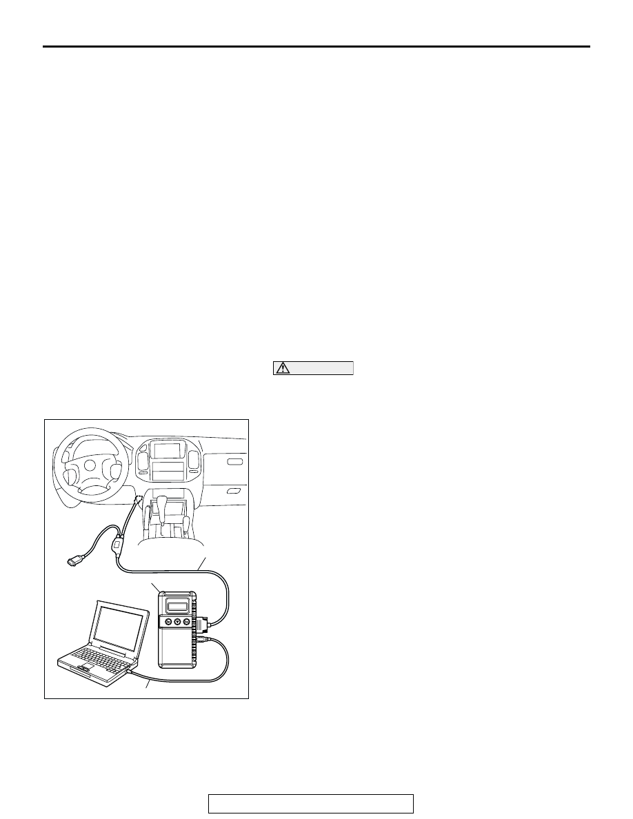
1. Ensure that the ignition switch is at the "LOCK" (OFF) 

position.

2. Start up the personal computer.
3. Connect special tool MB991827 to special tool MB991824 

and the personal computer.

4. Connect special tool MB991911 to special tool MB991824.
5. Connect special tool MB991911 to the data link connector.
6. Turn the power switch of special tool MB991824 to the "ON" 

position.
NOTE: When special tool MB991824 is energized, special 
tool MB991824 indicator light will be illuminated in a green 
color.

7. Start the MUT-III system on the personal computer.

NOTE: Disconnecting scan tool MB991958 is the reverse of 
the connecting sequence, making sure that the ignition 
switch is at the "LOCK" (OFF) position.

HOW TO READ AND ERASE DIAGNOSTIC 
TROUBLE CODES

Required Special Tools:

• MB991958: Scan Tool (MUT-III Sub Assembly)

AC306409AF

MB991911

MB991824

MB991827

IGNITION SWITCH

TSB Revision

CHASSIS ELECTRICAL

54A-10

• MB991824: Vehicle Communication Interface (V.C.I.)

• MB991827: MUT-III USB Cable

• MB991911: MUT-III Main Harness B

CAUTION

To prevent damage to scan tool MB991958, always turn the 
ignition switch to the "LOCK" (OFF) position before con-
necting or disconnecting scan tool MB991958.
NOTE: If the battery voltage is low, diagnostic trouble codes will 
not be set. Check the battery if scan tool MB991958 does not 
display.
1. Connect scan tool MB991958 to the data link connector.
2. Turn the ignition switch to "ON" position.
3. Select "Interactive Diagnosis" from the start-up screen.
4. Select "System select."
5. Choose "IMMOBILIZER" from the "POWER TRAIN" tab.
6. Select "MITSUBISHI".
7. Select "Diagnostic Trouble Code."
8. If a DTC is set, it is shown.
9. Choose "Erase DTCs" to erase the DTC.

HOW TO READ DATA LIST

Required Special Tools:

• MB991958: Scan Tool (MUT-III Sub Assembly)

• MB991824: Vehicle Communication Interface (V.C.I.)

• MB991827: MUT-III USB Cable

• MB991911: MUT-III Main Harness B

CAUTION

To prevent damage to scan tool MB991958, always turn the 
ignition switch to the "LOCK" (OFF) position before con-
necting or disconnecting scan tool MB991958.

AC306409AF

MB991911

MB991824

MB991827

IGNITION SWITCH

TSB Revision

CHASSIS ELECTRICAL

54A-11

1. Connect scan tool MB991958 to the data link connector.
2. Turn the ignition switch to "ON" position.
3. Select "Interactive Diagnosis" from the start-up screen.
4. Select "System select."
5. Choose "IMMOBILIZER" from the "POWER TRAIN" tab.
6. Select "Data List."
7. Choose an appropriate item and select the "OK" button.

DIAGNOSTIC TROUBLE CODE CHART

M1543007100451

CAUTION

During diagnosis, a DTC code associated with 
other system may be set when the ignition switch 
is turned on with connector(s) disconnected. On 
completion, confirm all systems for DTC code(s). 
If DTC code(s) are set, erase them all.
Use the following chart to develop proper diagnostic 
strategy.

AC306409AF

MB991911

MB991824

MB991827

DIAGNOSTIC 
TROUBLE CODE NO.

DESCRIPTION

REFERENCE PAGE

11

Transponder communication system or radio interference 
of encrypted code

P.54A-12

12

Encrypted codes are not the same or are not registered

P.54A-15

IGNITION SWITCH

TSB Revision

CHASSIS ELECTRICAL

54A-12

DIAGNOSTIC TROUBLE CODE PROCEDURES

DTC 11: Transponder Communication System or Radio Interference of Encrypted Code

.

CIRCUIT OPERATION
The ignition key is powered by the ignition key ring 
antenna. The ignition key then sends an encrypted 
code. The ignition key ring antenna receives the 
encrypted code, and determines if the ignition key is 
registered.

.

DTC SET CONDITION

• DTC 11 may be set if other ignition keys are in the 

vicinity of the vehicle as it is being started.

• The transponder’s encrypted code is not sent to 

the immobilizer-ECU immediately after the igni-
tion switch is turned to "ON" position.

NOTE: DTC 11 is always set together with MFI sys-
tem DTC P1610.

.

TROUBLESHOOTING HINTS

• Radio interference of the encrypted code

• Malfunction of the transponder

• Malfunction of the ignition key ring antenna

• Malfunction of the immobilizer-ECU

• Damaged wiring harness of connectors

.

DIAGNOSIS 

Required Special Tools:

• MB991223: Harness Set

• MB991958: Scan Tool (MUT-III Sub Assembly)

IMMOBILIZER-
ECU

IGNITION KEY
RING ANTENNA

TRANSPONDER

HIGH FREQUENCY
CIRCUIT

Ignition Key Ring Antenna Circuit

AC204170

CONNECTOR : D-121

DN

AC204172

CONNECTOR : D-201

AJ


Content   ..  508  509  510  511   ..