Mitsubishi Montero (2004+). Manual - part 509


  Index      Mitsubishi     Mitsubishi Montero - service repair manual 2004 year


Search            


Content   ..  507  508  509  510   ..


Mitsubishi Montero (2004+). Manual - part 509


BATTERY

TSB Revision

CHASSIS ELECTRICAL

54A-5

BATTERY

ON-VEHICLE SERVICE

BATTERY CHECK

M1541001000193

WARNING

Battery posts, terminals and related accessories con-
tain lead and lead compounds. WASH HANDS AFTER 
HANDLING.

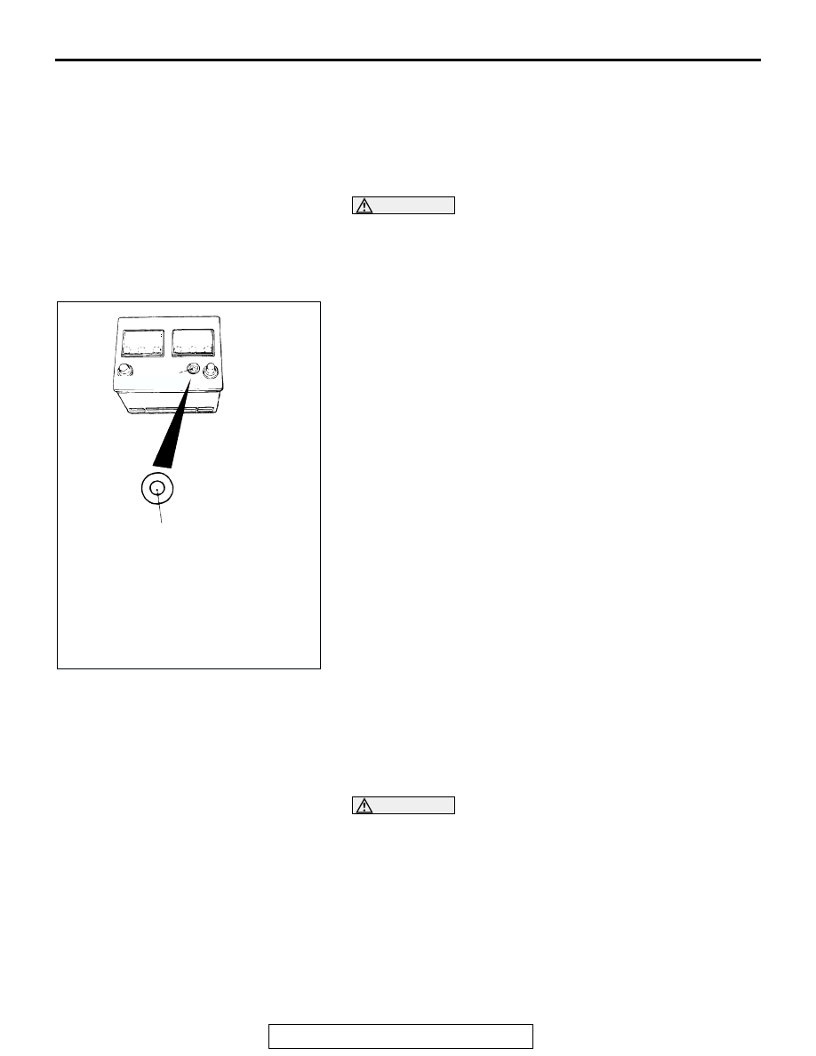
BATTERY VISUAL INSPECTION (1) 

The battery contains a visual test indicator which gives a green 
signal when an adequate charge level exists, and a dark signal 
when charging is required.

BATTERY VISUAL INSPECTION (2) 

Make sure ignition switch is in "LOCK" (OFF) position and all 
battery fed accessories are OFF.
1. Disconnect the negative cable from battery before 

disconnecting the positive cable.

WARNING

Care should be taken in the event battery case is 
cracked or leaking to protect hands from the electro-
lyte. A suitable pair of rubber gloves (not the house-
hold type) should be worn when removing battery by 
hand.

2. Remove the battery from the vehicle.
3. Inspect battery carrier for damage caused by loss of acid 

from battery. If acid damage is present, it is necessary to 
clean area with a solution of clean warm water and baking 
soda. Scrub area with a stiff bristle brush. Wipe clean with a 
cloth moistened with ammonia or baking soda in water.

ACX01557

INDICATOR

AB

DARK EYE:CHARGING NECESSARY
GREEN:GOOD CONDITION

BATTERY

TSB Revision

CHASSIS ELECTRICAL

54A-6

4. Clean the battery, especially the top with same solutions as 

described in step 3.

5. Inspect the battery case and cover for cracks. If cracks are 

present, battery must be replaced.

6. Clean the battery post with a suitable battery post cleaning 

tool.

7. Clean the inside surfaces of the terminal clamps with a 

suitable battery terminal cleaning tool. Replace damaged or 
frayed cables and broken terminal clamps.

8. Install the battery in the vehicle.
9. Connect the positive and negative cables to the battery in 

the order of mention.

10.Tighten the clamp nut securely.

BATTERY CHARGING

M1541001100543

WARNING

When batteries are being charged, an explosive gas forms beneath the cover of each cell. Do 
not smoke near batteries on charge or which have recently been charged. Do not break live 
circuits at the terminals of the batteries on charge. A spark will occur where the live circuit is 
broken. Keep all open flames away from the battery.

Battery electrolyte temperature may temporarily be allowed to rise to 55

°C (131°F). Increase of electrolyte 

temperature above 55

°C (131°F) is harmful to the battery, causing deformation of battery cell, decrease in life 

of battery, etc.

CHARGE RATE 

If the test indicator is dark, the battery should be charged as outlined below. When the dot appears or when 
maximum charge shown below is reached, charging should be stopped.

.

Charge Rate Chart

BATTERY TEST

M1541001200540

BATTERY TESTING PROCEDURE

STEP 1. Check the battery cables.

Remove the negative cable, then the positive cable.
Check for dirty or corroded connections.

Q: Are the battery cables dirty or have corroded 

connections?

YES : 

Clean the battery cables. Then go to Step 2.

NO : 

Go to Step 2.

STEP 2. Check the battery post.

Check for loose battery post.

Q: Are the battery post faulty? 

Yes : 

Replace the battery. Then go to Step 4.

NO : 

Go to Step 3.

STEP 3. Check the battery case and cover.
(1) )Remove the hold-downs and shields.
(2) Check for broken/cracked case or cover.

Q: Is the battery case or cover faulty?

YES : 

Replace the battery. Then go to Step 4.

NO : 

Go to Step 4.

BATTERY

80D26L-MF

Slow charging

5 amps 12 hours
10 amps 6 hours

Fast charging

20 amps 2.5 hours
30 amps 0.5 hours

IGNITION SWITCH

TSB Revision

CHASSIS ELECTRICAL

54A-7

STEP 4. Check the open circuit voltage.
(1) Turn headlights on for 15 seconds.
(2) Turn headlights off for two minutes to allow 

battery positive voltage to stabilize.

(3) Disconnect the battery cables.
(4) Read open circuit voltage.

Q: Is open circuit voltage 12.4 volts or more?

YES : 

Go to Step 5.

NO : 

Charge the battery at 5 amps for 15 hours. 
Then re-test.

STEP 5. Check the load test.
(1) Connect a load tester to the battery.
(2) Load the battery at the recommended discharge 

rate (See LOAD TEST RATE CHART) for 15 
seconds.

(3) Read voltage after 15 seconds, then remove 

load.

(4) Compare the measured value with the minimum 

voltage (See LOAD TEST CHART).

Q: Is the voltage higher than minimum voltage?

YES : 

The battery is normal.

NO : 

Replace the battery. Then go to Step 4.

LOAD TEST CHART

LOAD TEST RATE CHART

IGNITION SWITCH

GENERAL DESCRIPTION 

M1543009901371

IGNITION KEY REMINDER TONE ALARM

The ignition key reminder tone alarm will sound 
under the following condition, and warn the driver to 
remove the ignition key.

• The driver's door is opened when the ignition 

switch is at "LOCK" (OFF) or "ACC" position with-
out removing the ignition key.

However, the light reminder tone alarm will take pre-
cedence over this function.

IMMOBILIZER SYSTEM

The immobilizer system consists of the ignition key, 
the key ring antenna, the immobilizer-ECU, and the 
PCM. The ignition key has a built-in transponder. The 
key ring antenna is installed on the steering lock key 
cylinder. Only the registered ignition key permits the 
engine to start, therefore, the engine can never be 
started by means of a forged key or by connecting 
the ignition wiring directly. The system is significantly 
safe and reliable against theft. In addition, the driver 
has only to turn the ignition switch to the "ON" posi-
tion to activate the immobilizer system. If the require-
ments for starting the engine are not satisfied, the 
engine will be immobilized. If the ignition key is lost 
or another ignition key is added, the encrypted code 
can be registered or erased by using scan tool. 

TEMPERATURE 
°C (°F)

21 (70) AND 
ABOVE

16 (60)

10 (50)

4 (40)

1 (30)

7 (20)

12 (10) 18 (0)

Minimum voltage

9.6

9.5

9.4

9.3

9.1

8.9

8.7

8.5

Load test

300 amps

Cranking ratio (0

°F)

582 amps

Reserve capacity

133 minutes

Application

80D26L-MF

IGNITION SWITCH

TSB Revision

CHASSIS ELECTRICAL

54A-8

CAUTION WHEN REPLACING IMMOBILIZER SYSTEM RELATED PARTS
To replace immobilizer system related parts, refer to the table below. When the ignition key is re-registered 
with scan tool MB991958, the originally registered ignition key registration information will be lost.

IGNITION KEY REMINDER TORN ALARM DIAGNOSIS

M1543000700678

The Ignition key reminder tone alarms is controlled 
by the Simplified Wiring System (SWS). For trouble-
shooting, refer to GROUP 54B, SWS Diagnosis 

P.54B-22

.

IMMOBILIZER SYSTEM DIAGNOSIS

INTRODUCTION TO IMMOBILIZER SYSTEM DIAGNOSIS

M1543009901025

CAUTION

The encrypted code should always be re-regis-
tered when replacing the immobilizer-ECU.
The immobilizer system consists of the immobi-
lizer-ECU, PCM, ignition key and ignition key ring 
antenna. If the engine cannot be started by using a 
registered ignition key, one of these components 
may be defective. If the immobilizer system has 
immobilized the engine, MFI system DTC P1610 will 
be output. In this case, observe the immobilizer sys-
tem troubleshooting.

IMMOBILIZER SYSTEM DIAGNOSTIC TROUBLESHOOTING STRATEGY

M1543006900700

Use the following steps to plan your diagnostic strat-
egy.
1. Gather information about the problem from the 

customer.

2. Verify that the condition as described by the 

customer exists.

3. Check the vehicle for any immobilizer system 

DTCs.

4. If you cannot verify the condition and there are no 

immobilizer system DTCs, the malfunction is 
intermittent. Refer to GROUP 00, How to Use 
Troubleshooting/inspection Service Points 

− How 

to Cope with Intermittent Malfunctions 

P.00-6

.

5. If you can verify the condition but there are no 

immobilizer system DTCs, or the system cannot 
communicate with scan tool MB991958, refer to 
Symptom Chart and find the fault 

P.54A-15

.

ITEM

PCM

IMMOBILIZER-ECU

IGNITION KEY

When replacing PCM

-

Replacement is not 
required

Replacement is not required. 
Re-registration are required.

When rewriting PCM

-

Replacement is not 
required

Replacement is not required. 
Re-registration is not required.

When replacing 
immobilizer-ECU

Replacement not 
required

-

Replacement is not required. 
Re-registration is required.

When adding ignition keys 
newly (if registered ignition 
keys are not lost)

Replacement not 
required

Replacement is not 
required

Register only additional ignition 
keys to be registered.

When adding ignition key 
newly (if registered ignition 
keys are lost)

Replacement not 
required

Replacement is not 
required

Register ignition key to be 
added and re-register all other 
ignition keys.

When ignition key is lost

Replacement not 
required

Replacement is not 
required

Re-register all other ignition 
keys except the lost one.


Content   ..  507  508  509  510   ..