Mitsubishi Montero (2004+). Manual - part 373
MULTIPORT FUEL INJECTION (MFI) DIAGNOSIS
TSB Revision
MULTIPORT FUEL INJECTION (MFI)
13A-979
INJECTOR
Required Special Tool:
• MD998474: Test Harness
.
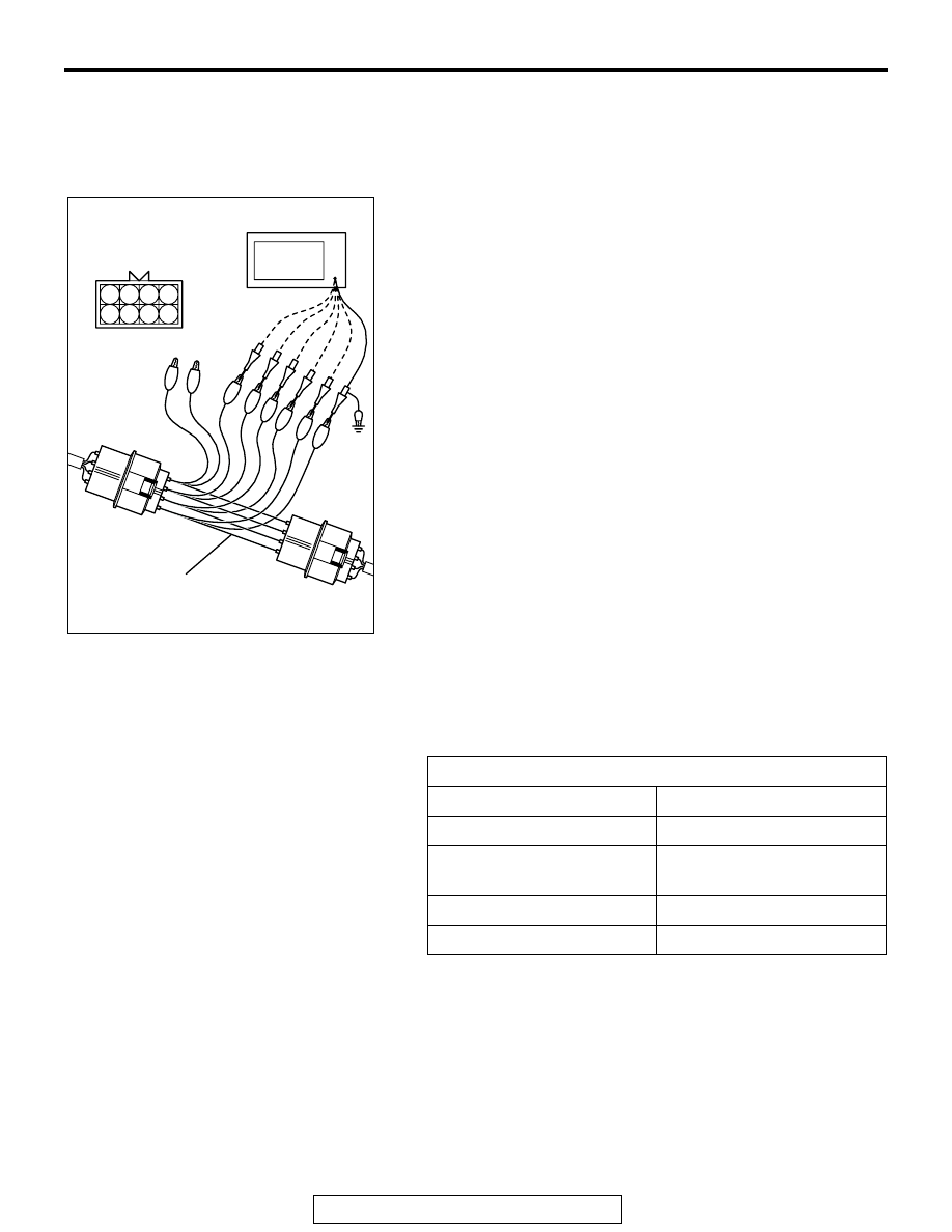
Measurement Method
1. Disconnect the injector intermediate connector, and connect
the test harness special tool (MD998474) in between.
2. Connect the oscilloscope probe to each injector
intermediate connector terminal to analyze each cylinder:
• Terminal No. 3 (green clip of special tool) for the number 1
cylinder
• Terminal No. 2 (white clip) for the number 2 cylinder
• Terminal No. 1 (blue clip) for the number 3 cylinder
• Terminal No. 7 (yellow clip) for the number 4 cylinder
• Terminal No. 6 (red clip) for the number 5 cylinder
• Terminal No. 5 (black clip) for the number 6 cylinder
.
Alternate method (Test harness not available)
1. Connect the oscilloscope probe to PCM terminal No. 1.
(When checking the number 1 cylinder.)
2. Connect the oscilloscope probe to PCM terminalNo. 5.
(When checking the number 2 cylinder.)
3. Connect the oscilloscope probe to PCM terminal No. 14.
(When checking the number 3 cylinder.)
4. Connect the oscilloscope probe to PCM terminal No. 21.
(When checking the number 4 cylinder.)
5. Connect the oscilloscope probe to PCM terminal No. 2.
(When checking the number 5 cylinder.)
6. Connect the oscilloscope probe to PCM terminal No. 6.
(When checking the number 6 cylinder.)
Standard Wave Pattern
Observation conditions
Function
Special pattern
Pattern height
Variable
Variable knob
Adjust while viewing the
wave pattern
Pattern selector
Display
Engine r/min
Idle speed
AK102982 AB
OSCILLOSCOPE
INJECTOR
INTERMEDIATE
CONNECTOR
MD998474
1 2 3 4
5 6 7 8