Content .. 1169 1170 1171 1172 ..
Mitsubishi Montero (2004+). Manual - part 1171
SERVICE PRECAUTIONS
TSB Revision
SUPPLEMENTAL RESTRAINT SYSTEM (SRS)
52B-19
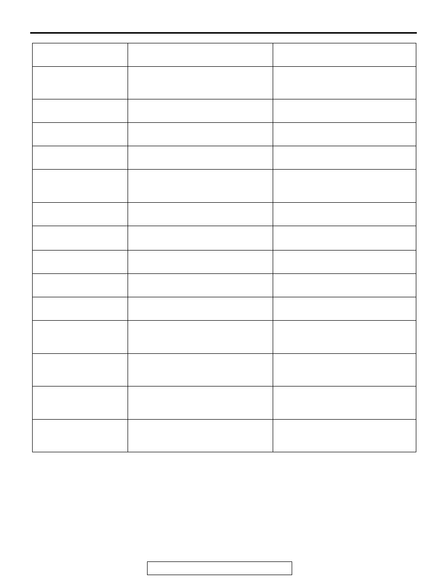
SRS-ECU TERMINAL
NO.
DESTINATION OF HARNESS
CORRECTIVE ACTION
1, 2, 3, 4
Instrument panel wiring harness
→
Front wiring harness
→ Front impact
sensor
Correct or replace each wiring harness.
7
Instrument panel wiring harness
→
Ground
Correct or replace the instrument panel
wiring harness.
8
Instrument panel wiring harness
→ SRS
warning light
Correct or replace the instrument panel
wiring harness.
9, 10
Instrument panel wiring harness
→ Air
bag module (Front passenger's side)
Correct or replace the instrument panel
wiring harness.
11, 12
Instrument panel wiring harness
→
Clock spring
→ Air bag module
(Driver's side)
Correct or replace each wiring harness.
Replace the clock spring.
13
Instrument panel wiring harness
→
Junction block (fuse No.8)
Correct or replace the instrument panel
wiring harness.
16
Instrument panel wiring harness
→Function block (fuse No.6)
Correct or replace the instrument panel
wiring harness.
20
Instrument panel wiring harness
→
Data link connector
Correct or replace the instrument panel
wiring harness.
21, 22
Side-airbag wiring harness
→
Side-airbag module (LH)
Correct or replace the side air bag
wiring harness.
23, 24
Side-airbag wiring harness
→
Side-airbag module (RH)
Correct or replace the side air bag
wiring harness.
27, 28
Side-airbag wiring harness
→ Floor
wiring harness
→ Seat belt
pre-tensioner (RH)
Correct or replace each wiring harness.
29, 30
Side-airbag wiring harness
→ Floor
wiring harness
→ Seat belt
pre-tensioner (LH)
Correct or replace each wiring harness.
34, 36
Side-airbag wiring harness
→ Floor
wiring harness
→ Side impact sensor
(LH)
Correct or replace each wiring harness.
40, 42
Side-airbag wiring harness
→ Floor
wiring harness
→ Side impact sensor
(RH)
Correct or replace each wiring harness.