Mitsubishi Montero (2004+). Manual - part 1031


  Index      Mitsubishi     Mitsubishi Montero - service repair manual 2004 year


Search            


Content   ..  1029  1030  1031  1032   ..


Mitsubishi Montero (2004+). Manual - part 1031


ON-VEHICLE SERVICE

TSB Revision

BASIC BRAKE SYSTEM

35A-123

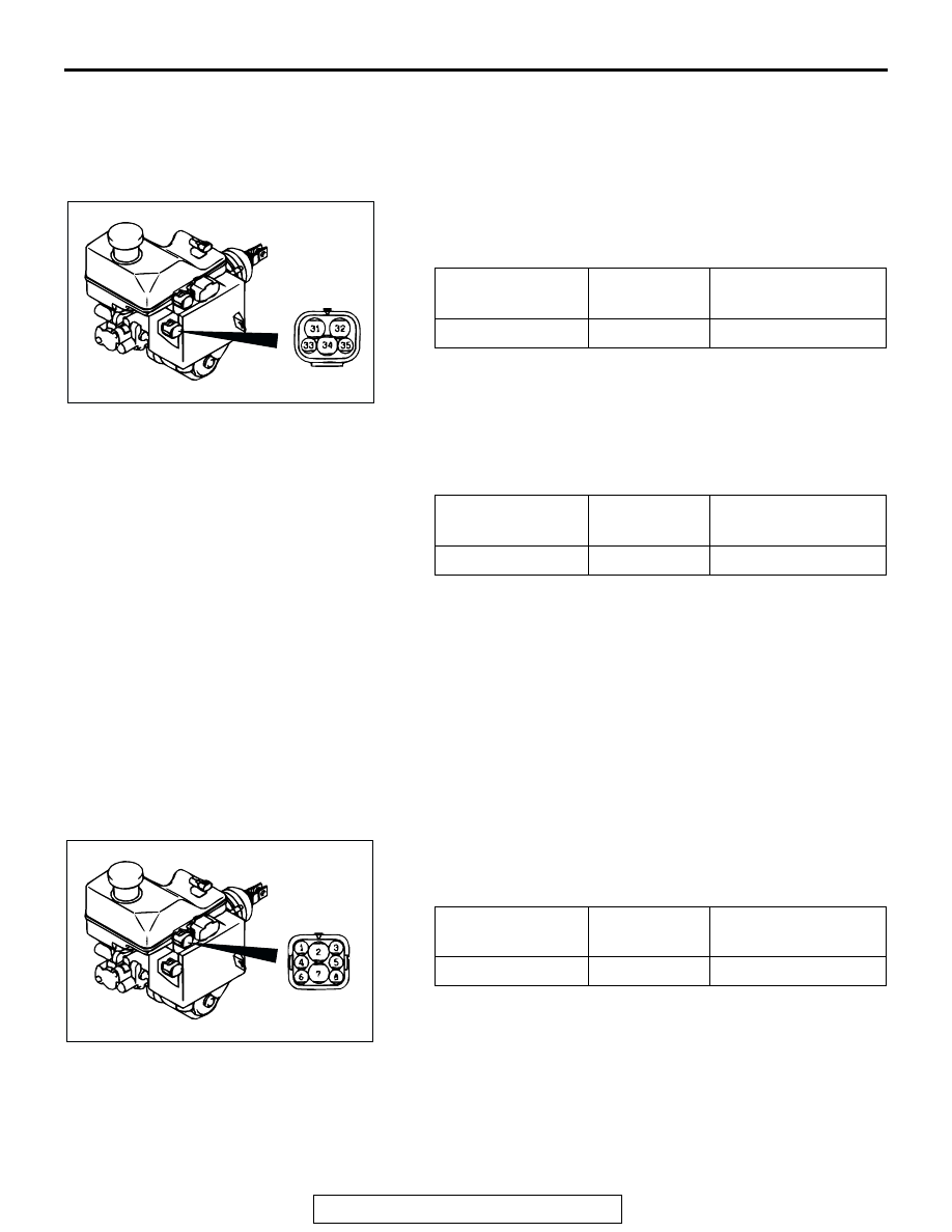
Pressure Switch (for Pump Control) Check

1. Depress the brake pedal repeatedly more than 40 times until 

the pedal depressing force feels heavy with the ignition 
switch at the "LOCK" (OFF) position to release the pressure 
of HBB power supply system.

2. Disconnect the HBB connector "A."
3. Measure the resistance between terminals No. 33 and No. 

35 at the HBB connector "A." 

4. If the resistance value exceeds the specified value, replace 

the HBB master cylinder and hydraulic unit assembly.

5. With the HBB connector "A" disconnected, turn "ON" the 

ignition switch to operate the pump motor. Then measure 
the resistance between terminals No. 33 and No. 35 at the 
HBB connector "A" while the pump motor is operating.

6. If the resistance value exceeds the specified value, replace 

the HBB master cylinder and hydraulic unit assembly.

7. Connect the HBB connector "A."
8. Erase HBB diagnostic trouble codes (Refer to 

P.35A-13

).

Pressure Switch (for Low-Pressure Warning) 
Check

1. Depress the brake pedal repeatedly more than 40 times until 

the pedal depressing force is felt heavy with the ignition 
switch at the "LOCK" (OFF) position to release the pressure 
of HBB power supply system.

2. Disconnect the HBB connector "B."
3. Measure the resistance between terminals No. 1 and No. 5 

at the HBB connector "B." 

4. If the resistance value exceeds the specified value, replace 

the HBB master cylinder and hydraulic unit assembly.

5. Next, turn the ignition switch to the "ON" position to operate 

the pump motor. Then confirm that the pump motor is 
stopped.

6. Measure the resistance between terminals No. 1 and No. 5 

at the HBB connector "B." 

TESTER 
CONNECTION

SPECIFIED 
CONDITION

RESISTANCE 
VALUE k

33 

− 35

Continuity

Approximately 1

TESTER 
CONNECTION

SPECIFIED 
CONDITION

RESISTANCE 
VALUE 

33 

− 35

Continuity

Less than 2

ACX01809

CONNECTOR  A

AC

TESTER 
CONNECTION

SPECIFIED 
CONDITION

RESISTANCE 
VALUE k

− 5

Continuity

Approximately 5.7

ACX01810 AC

CONNECTOR B

ON-VEHICLE SERVICE

TSB Revision

BASIC BRAKE SYSTEM

35A-124

7. If the resistance value exceeds the specified value, replace 

the HBB master cylinder and hydraulic unit assembly.

8. Connect the HBB connector "B."
9. Erase HBB diagnostic trouble codes (Refer to 

P.35A-13

).

HBB MOTOR RELAY CHECK

M1351010600059

Motor Relay A, B

CAUTION

Apply battery voltage according to the table below. Never 
confuse the positive and negative battery terminals, or the 
diode inside the relay will be damaged.

TESTER 
CONNECTION

SPECIFIED 
CONDITION

RESISTANCE 
VALUE k

− 5

Continuity

Approximately 1

BATTERY CONNECTION TESTER 

CONNECTION

SPECIFIED 
CONDITION

− 5

Open circuit

• Connect battery terminal 

(+) to terminal 3

• Connect battery terminal 

(

−) to terminal 1

− 5

Less than 2 
ohms

AC204381

4

1

3

5

AC204329

ACX01808

AB

MOTOR
RELAY B

BRAKE FLUID
RESERVOIR

MOTOR
RELAY A

ON-VEHICLE SERVICE

TSB Revision

BASIC BRAKE SYSTEM

35A-125

BRAKE FLUID LEVEL INSPECTION AND BLEEDING

M1351001400477

CAUTION

• Use only brake fluid DOT3 or DOT4. Never mix the specified brake fluid with other brake fluid, as it 

will significantly decrease braking performance.

• Depress the brake pedal slowly. If the brake pedal is pressed too quickly, the pump motor will acti-

vate frequently and a large volume of high-pressure brake fluid may flow from the brake caliper 
quickly, depleting the HBB reservoir contents and possibly introducing air into the HBB system.

• Depending upon the quantity of brake fluid in the reservoir, if the brake pedal is pressed with the 

reservoir cap removed, the brake fluid in the reservoir may overflow.

• Use suitable protection to prevent brake fluid from contacting underhood components and body 

paint.

HBB System Bleeding

WARNING

The HBB system bleeding must be done in the follow-
ing cases.

If brake fluid is drained after removing or installing 
the HBB

if there is excessive brake fluid loss during normal 
brake system bleeding

if you suspect that air has entered the HBB system

NOTE: The HBB brake system bleeding procedure requires 
two persons working together.
HBB system bleeding must be done in the following order:

HBB SYSTEM BLEEDING STEPS

1.

FRONT BRAKE LINES (FILLING)

2.

ACCUMULATOR (HBB)

3.

REAR BRAKE LINES (FILLING)

4.

POWER SUPPLY (HBB)

5.

ABS (HBB)

6.

REAR BRAKE LINES (BLEEDING)

7.

FRONT BRAKE LINES (BLEEDING)

ON-VEHICLE SERVICE

TSB Revision

BASIC BRAKE SYSTEM

35A-126

CAUTION

• Keep the brake fluid reservoir level just above the 

"MIN" line. Monitor the fluid level during this procedure 
to ensure the fluid does not reach below the "MIN" line, 
to prevent air from entering the system.

• If a large quantity of brake fluid is drained during the 

bleeding procedure, the accumulator pressure will 
decrease abnormally. Do not bleed more than 0.1 dm

3


(0.11quart) from each wheel at a time.

• Confirm that the pump motor stops after each air-bleed-

ing step. If not, proceed to the troubleshooting the HBB 
System section.

NOTE: The buzzer may sound during this procedure due to low 
pressure in the system. The buzzer will stop when normal HBB 
pressure is restored.

Required Special Tools:

•  MB991958: Scan Tool (MUT-III Sub Assembly)

• MB991824: Vehicle Communication Interface (V.C.I.)

• MB991827: MUT-III USB Cable

• MB991911: MUT-III Main Harness B

1. Fill the front brake system with brake fluid as follows (RH 

first, LH second):

(1) Attach a clear hose to the RH caliper bleeder valve. This 

helps to monitor air/fluid flow.

(2) Be sure the fluid level is between the "MIN" and "MAX" 

lines.

(3) Turn the ignition switch to the "LOCK" (OFF) position. 

Pump the brake pedal 3 

− 4 times and hold it depressed.

(4) Open the RH caliper bleeder valve 1/4 turn.
(5) With the bleeder valve still open, pump the brake pedal 

repeatedly to fill the line with fluid until no obvious air 
bubbles are seen. When no more obvious air bubbles are 
seen, and while the brake pedal is still being pumped, 
close the bleeder valve.

(6) Repeat steps (1) 

− (5) for the LH caliper.

(7) Release the brake pedal when both sides are filled.

2. Fill the pump motor as follows:

(1) Turn the ignition switch to the "ON" position to operate 

the pump motor.
a. If the pump motor operates normally (normal operation 

sound), go to step 3.

b. If the pump motor operation sound is dry and 

high-pitched, depress the brake pedal 3 or 4 times to 
introduce fluid into the pump motor. Then go to step 3.

3. Fill the accumulator system with brake fluid as follows:

(1) Wait for the pump motor to stop from step 2.
(2) Depress the brake pedal slowly 3 or 4 times with the 

ignition switch at the "ON" position. Observe the condition 
of the brake fluid in the reservoir.
a. If the fluid is cloudy, leave it for 2 or 3 minutes until it 

becomes clear.


Content   ..  1029  1030  1031  1032   ..