Mitsubishi Montero (2002-2004). Manual - part 959


  Index      Mitsubishi     Mitsubishi Montero - service repair manual 2002-2004 year


Search            


Content   ..  957  958  959  960   ..


Mitsubishi Montero (2002-2004). Manual - part 959


DIAGNOSTIC TROUBLE CODE PROCEDURES <TRANSFER>

TSB Revision

DIAGNOSTIC TROUBLE CODE PROCEDURES

23Ac-319

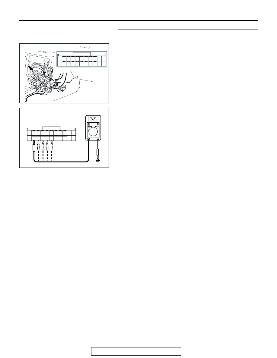
STEP 5. Measure the switch output voltage at transfer-ECU 
connector E-104 by backprobing.
(1) Do not disconnect connector E-104.
(2) Turn the ignition switch to the "ON" position.

(3) Measure the voltage between terminals 43 44, 45, 46, 47 

and ground by backprobing.

• The voltage should measure battery positive voltage.

(4) Turn the ignition switch to the "LOCK" (OFF) position.
Q: Is the measured voltage battery positive voltage?

YES : Go to Step 8.
NO :  Go to Step 6.

AC204176

CONNECTOR : E-104

BA

51

40

3839

50

41

52

48

37

46

35

47

36

45

34

43

32

44

33

49

42

31

AC204918 BX

E-104 HARNESS CONNECTOR : 
HARNESS SIDE

51

40

3839

50

41

52

48

37

46

35

47

36

45

34

43

32

44

33

49

42

31

DIAGNOSTIC TROUBLE CODE PROCEDURES <TRANSFER>

TSB Revision

DIAGNOSTIC TROUBLE CODE PROCEDURES

23Ac-320

STEP 6. Check each detection switch connectors C-05, C-
06, C-10, C-11, C-12 and transfer-ECU connector E-104 for 
loose, corroded or damaged terminals, or terminals 
pushed back in the connector.
Q: Are the connectors and terminals in good condition?

YES : Go to Step 7.
NO :  Repair or replace the damaged components. Refer to 

GROUP 00E, Harness Connector Inspection 

P.00E-

2

.

AC204510

CONNECTORS : C-05, C-06, C-10, C-11, C-12

C-05 (BR)

C-05

C-06 (B)

C-06

C-10 (B)

C-10   

C-11 (W)

C-11

C-12 (BR)

C-12

AC

1

1

1

1

1

AC204176

CONNECTOR : E-104

BA

51

40

3839

50

41

52

48

37

46

35

47

36

45

34

43

32

44

33

49

42

31

DIAGNOSTIC TROUBLE CODE PROCEDURES <TRANSFER>

TSB Revision

DIAGNOSTIC TROUBLE CODE PROCEDURES

23Ac-321

STEP 7. Check harnesses for short circuit to ground 
between each detection switch connectors C-05, C-06, C-
10, C-11, C-12 terminal 1 and transfer-ECU connector E-104 
terminals 43, 44, 45, 46, 47.
Q: Are the harnesses wire in good condition?

YES : Go to Step 11.
NO :  Repair or replace the harness wire.

AC204510

CONNECTORS : C-05, C-06, C-10, C-11, C-12

C-05 (BR)

C-05

C-06 (B)

C-06

C-10 (B)

C-10   

C-11 (W)

C-11

C-12 (BR)

C-12

AC

1

1

1

1

1

AC204176

CONNECTOR : E-104

BA

51

40

3839

50

41

52

48

37

46

35

47

36

45

34

43

32

44

33

49

42

31

DIAGNOSTIC TROUBLE CODE PROCEDURES <TRANSFER>

TSB Revision

DIAGNOSTIC TROUBLE CODE PROCEDURES

23Ac-322

STEP 8. Check each detection switch connectors C-05, C-
06, C-10, C-11, C-12 and transfer-ECU connector E-104 for 
loose, corroded or damaged terminals, or terminals 
pushed back in the connector.
Q: Are the connectors and terminals in good condition?

YES : Go to Step 9.
NO :  Repair or replace the damaged components. Refer to 

GROUP 00E, Harness Connector Inspection 

P.00E-

2

.

AC204510

CONNECTORS : C-05, C-06, C-10, C-11, C-12

C-05 (BR)

C-05

C-06 (B)

C-06

C-10 (B)

C-10   

C-11 (W)

C-11

C-12 (BR)

C-12

AC

1

1

1

1

1

AC204176

CONNECTOR : E-104

BA

51

40

3839

50

41

52

48

37

46

35

47

36

45

34

43

32

44

33

49

42

31


Content   ..  957  958  959  960   ..