Mitsubishi Montero (2002-2004). Manual - part 859
ON-VEHICLE SERVICE
TSB Revision
AUTOMATIC TRANSMISSION
23Aa-27
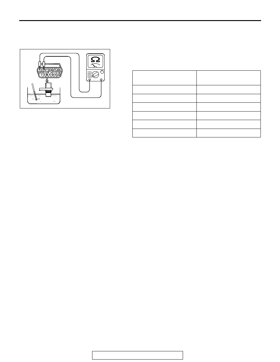
TRANSMISSION FLUID TEMPERATURE SENSOR
CHECK
M1231104500158
1. Remove the transmission fluid temperature sensor.
2. Measure the resistance between terminals No.1 and No.2 of
the transmission fluid temperature sensor connector.
Standard value:
3. If the transmission fluid temperature sensor resistance is
outside the specified range and the "A/T TEMP" indicator
light is illuminating, replace the transmission fluid
temperature sensor.
NOTE: The "A/T TEMP" indicator light on the combination
meter illuminating when the temperature reaches approxi-
mately 125
°
C (257
°
F) or greater, and then stops flashing
when the temperature drops below approximately 115
°
C
(238
°
F).
TRANSMISSION RANGE SWITCH CHECK
M1231112600105
Refer to
STOPLIGHT SWITCH CHECK
M1231103000127
Refer to GROUP 35A, On-vehicle Service
− Stoplight Switch
Check
VEHICLE SPEED SENSOR CHECK
M1231109800110
Refer to GROUP 54A, Combination Meters Assembly and
Vehicle Speed Sensor
.
DUAL PRESSURE SWITCH CHECK
M1231109900117
Refer to GROUP 55A, On-vehicle Service
− Dual Pressure
Switch Check
TRANSMISSION FLUID
TEMPERATURE
RESISTANCE
0
°C (32°F)
16.7
− 20.5 kΩ
20
°C (68°F)
7.3
− 8.9 kΩ
40
°C (104°F)
3.4
− 4.2 kΩ
60
°C (140°F)
1.9
− 2.2 kΩ
80
°C (176°F)
1.0
− 1.2 kΩ
100
°C (212°F)
0.57
− 0.69 kΩ
AC100601AB
ATF