Mitsubishi Montero (2002-2004). Manual - part 858


  Index      Mitsubishi     Mitsubishi Montero - service repair manual 2002-2004 year


Search            


Content   ..  856  857  858  859   ..


Mitsubishi Montero (2002-2004). Manual - part 858


ON-VEHICLE SERVICE

TSB Revision

AUTOMATIC TRANSMISSION

23Aa-23

TRANSFER OIL REPLACEMENT

M1231112500108

1. Remove the filler plug.
2. Remove the drain plug and discharge the oil.
3. Tighten the drain plug to the specified torque.

Tightening torque: 32 

± 2 Nm (24 ± 1 ft-lb)

4. Fill in oil to the bottom of the filler plug hole.

Specified oil: Gear oil SAE 75W 

 90 or 75W  85W 

conforming to API classification GL-4

Quantity: 2.8 dm

3

 (3.0 quarts)

5. Tighten the filler plug to the specified torque.

Tightening torque: 32 

± 2 Nm (24 ± 1 ft-lb)

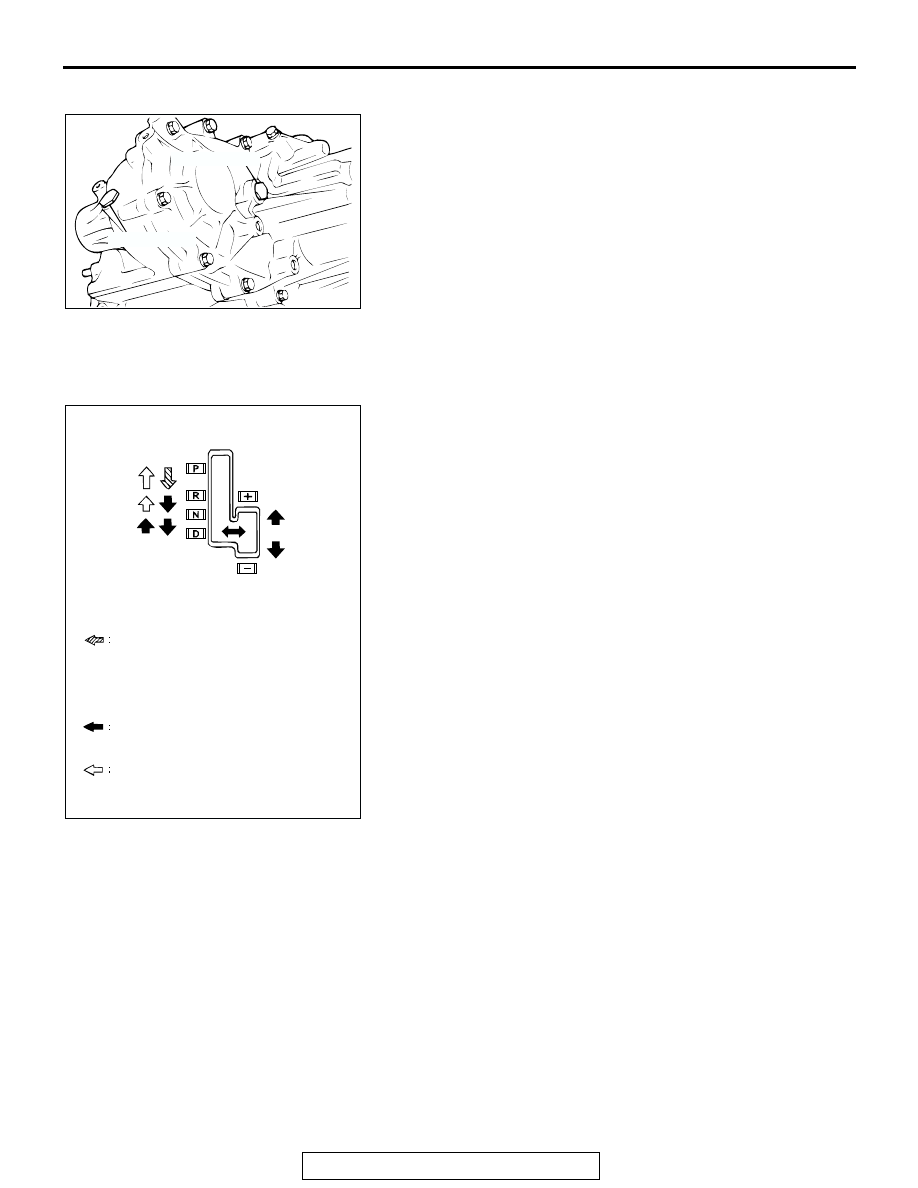
SELECTOR LEVER OPERATION CHECK

M1231001300288

1. Apply the parking brake, and check that the selector lever 

moves smoothly and accurately to each position.

2. Check that the engine starts when the selector lever is in the 

"N" or "P" position, and that it does not start when the 
selector lever is in any other position.

3. Start the engine, release the parking brake, and check that 

the vehicle moves forward when the selector lever is moved 
from the "N" position to 1st or 2nd gear in sport mode, and 
that the vehicle reverses when the selector lever is moved to 
the "R" position.

4. Stop the engine.
5. Turn the ignition switch to the "ON" position, and check that 

the backup lamp illuminates when the selector lever is 
shifted from the "P" to the "R" position.
NOTE: The A/T key interlock and shift lock mechanisms pre-
vent movement of the selector lever from the "P" position if 
the ignition switch is in a position other than "LOCK" (OFF) 
and the brake pedal is not depressed.

TRANSFER SHIFT LEVER OPERATION CHECK

M1231120800029

1. Check that the transfer shift lever moves smoothly and 

correctly to each transfer gear position when the lever is 
pushed downwards and moved.

2. Apply the parking brake, turn the ignition switch to the "ON" 

position and move the selector lever to "N" position.

ACX01200AB

DRAIN PLUG

FILLER PLUG

AC204938AB

THE SELECTOR LEVER MOVES WHEN THE 
BRAKE PEDAL IS DEPRESSED AND THE 
BUTTON IS PUSHED IN WITH THE
IGNITION KEY IN ANY POSITION OTHER
THAN THE "LOCK" (OFF) POSITION. 

THE SELECTOR LEVER MOVES WITHOUT 
PUSHING THE BUTTON.

THE SELECTOR LEVER MOVES WHEN THE 
BUTTON IS PUSHED.

ON-VEHICLE SERVICE

TSB Revision

AUTOMATIC TRANSMISSION

23Aa-24

3. Check that the 4WD indicator light illuminates, flashes or 

switches off according to the pattern shown in the illustration 
when the transfer shift lever is move to each transfer 
position.

4. If the selection is not completed even after 5 seconds or 

more have passed, carry out the following procedure.

(1) Return the transfer shift lever to the position it was at 

before selection.

(2) Start the engine, drive the vehicle straight forward, and 

then stop the engine.

(3) Apply the parking brake, and then move the selector 

lever to the "N" position.

(4) Operate the transfer shift lever once more.

NOTE: If the vehicle is not fully stopped or if the selector 
lever is at a position other than "N" position when select-
ing 4HLc or 4LLc, the 4WD indicator light will flash more 
quickly than normal, and the 4WD position will not be 
selected. This is a normal phenomenon which serves to 
control the smooth selection of 4HLc and 4LLc.

KEY INTERLOCK AND SHIFT LOCK MECHANISM 
CHECK

M1232003100078

1. Carry out the following inspection.

AC204124

4L

4L

4L

4L

4L

4L

4L

4L

4L

AB

: ON

: FLASHING

: OFF

2H

4H

4H

4HLc

4HLc

4LLc

<2H

4H>

<4H

4HLc>

<4HLc

4LLc>

BEFORE
SELECTION

DURING
SELECTION

SELECTION
COMPLETED

KEY INTERLOCK SIDE

INSPECTION 
PROCEDURE

INSPECTION 
REQUIREMENTS

INSPECTION ITEM (NORMAL CONDITION)

1

Brake pedal: 
Depressed

Ignition key position: 
"LOCK" (OFF) or removed

Unable to push in the selector lever push 
button and move the lever out of the "P" 
position.

2

Ignition key position: 
"ACC"

Able to push in the selector lever push 
button, move the lever out of the "P" 
position, and shift to any position.

3

Brake pedal: Not 
depressed

Selector lever: Other than 
"P" position

Unable to turn the ignition key to the 
"LOCK" (OFF) position.

4

Selector lever: "P" position Able to turn the ignition key to the 

"LOCK" (OFF) position.

ON-VEHICLE SERVICE

TSB Revision

AUTOMATIC TRANSMISSION

23Aa-25

2. When any of the above checks are not normal, adjust the 

shift lock cable unit in following procedure.

(1) Remove the front floor console. (Refer to GROUP 52A 

− 

Floor Console Assembly 

P.52A-7

.)

(2) Shift selector lever to "P" position.
(3) Turn the ignition key to "LOCK" (OFF) position.
(4) Loosen the bolt fixing the shift lock cable unit, push the 

lever in direction B and the unit in direction C and tighten 
the bolt at the standard torque.

Tightening torque: 5.0 

± 1.0 Nm (44 ± 9 in-lb)

(5) Lift the lock guide of the key interlocking cable and then 

unlock it.

(6) Lower the lock guide of the key interlocking cable and 

then lock it.
NOTE: The key interlocking cable is adjusted according 
to the lock position (cap push state) at this time. Readjust 
the lock position if key interlocking operations malfunction 
after locking.

3. After adjustment, re-check the operations. Replace the shift 

lock cable unit if operations are defective.(Refer to 

P.23Aa-

35

.)

TRANSMISSION CONTROL CABLE 
ADJUSTMENT

M1231119500024

1. Move the selector lever to the "N" position.

SHIFT LOCK SIDE

INSPECTION 
PROCEDURE

INSPECTION CONTENTS

CHECK DETAILS (NORMAL CONDITION)

1

Brake pedal: 
Not depressed

Ignition key 
position: "ACC"

When the selector lever push button is depressed, the 
selector lever can not be shifted out of the "P" position.

2

Brake pedal: 
Depressed

When the selector lever push button is depressed, the 
selector lever can be shifted smoothly to other position.

3

Brake pedal: 
Not depressed

When the selector lever push button is depressed, the 
selector lever can be shifted smoothly from the "R" 
position to the "P" position.

AC000004AB

LOCK

UNLOCK

LOCK GUIDE

KEY INTERLOCK CABLE

CAP

LEVER

FIXING BOLT

SHIFT LOCK CABLE UNIT

C

A

B

ON-VEHICLE SERVICE

TSB Revision

AUTOMATIC TRANSMISSION

23Aa-26

2. Loosen the upper control lever adjusting nut.
3. Check that the transmission range switch is at "N" position.
4. Adjust the upper control lever so that there is no slackness 

or excessive tightness in the transmission control cable, and 
then tighten the adjusting nut to the specified torque.

Tightening torque: 23 

± 4 Nm (17 ± 3 ft-lb)

5. Check that the transmission operation and functioning in 

each position corresponds accurately to the position of the 
selector lever.

TRANSFER-ECU CHECK

M1231120900037

1. Remove the indicator panel and the floor console front 

panel. (Refer to GROUP 52A 

− Floor Console 

P.52A-7

.)

2. Measure the transfer-ECU terminal voltage. (Refer to 

P.23Ab-53

.)

POSITION INDICATOR LIGHT CHECK

M1231121000026

1. Remove the indicator panel. (Refer to GROUP 52A 

− Floor 

Console 

P.52A-7

.)

2. Check that there is continuity between the following 

terminals: 

3. If the continuity is incorrect, replace the position indicator 

light unit assembly.

AUTOMATIC TRANSMISSION CONTROL 
COMPONENT CHECK

CRANKSHAFT POSITION SENSOR CHECK

M1231102700123

Refer to GROUP 13A, Diagnosis 

− Check Procedure With 

Oscilloscope.

P.13Ab-50

.

ACCELERATOR PEDAL POSITION SENSOR 
CHECK

M1231102800012

Refer to GROUP 13A, On-vehicle Service 

− Accelerator Pedal 

Position Sensor Check. 

P.13Ab-50

.

ACX01326AB

TRANSMISSION

UPPER 
CONTROL LEVER

FRONT

ADJUSTING NUT

AC000010AB

FLOOR 
CONSOLE

TRANSFER-ECU

TERMINAL NO.

NORMAL CONDITION

− 2

Less than 2 ohms

− 4

AC000011AB

INDICATOR 
PANEL


Content   ..  856  857  858  859   ..