Mitsubishi Montero (2002-2004). Manual - part 741


  Index      Mitsubishi     Mitsubishi Montero - service repair manual 2002-2004 year


Search            


Content   ..  739  740  741  742   ..


Mitsubishi Montero (2002-2004). Manual - part 741


TSB Revision

SYMPTOM PROCEDURES

13Ad-13

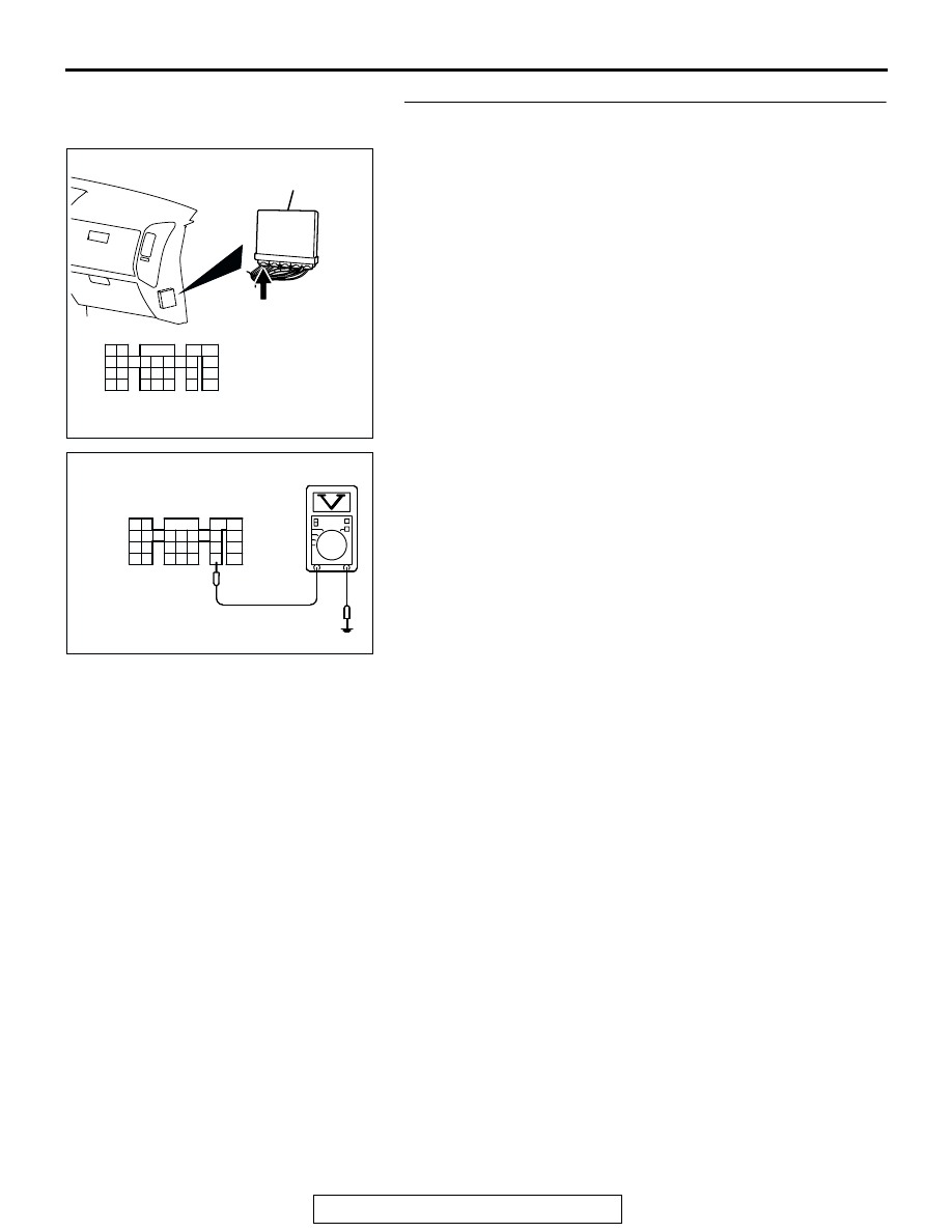
STEP 6. Measure the power supply voltage at PCM 
connector D-132.
(1) Disconnect the connector D-132 and measure at the 

harness side.

(2) Turn the ignition switch to the "ON" position.

(3) Measure the voltage between terminal No. 7 and ground.

•  Voltage should be battery positive voltage.

(4) Turn the ignition switch to the "LOCK" (OFF) position.
Q: Is battery positive voltage (approximately 12 volts) 

present?
YES : 
Replace the PCM. Then confirm that the malfunction 

symptom is eliminated.

NO :  Check harness connectors E-111 at intermediate 

connector for damage, and repair or replace as 
required. Refer to GROUP 00E, Harness Connector 
Inspection 

P.00E-2

If intermediate connectors E-111 

is in good condition, repair an open circuit between 
combination meter connector D-04 (terminal No. 38) 
and PCM connector D-132 (terminal No. 7). Then 
confirm that the malfunction symptom is eliminated.

AK200938

2

3

4

5

6

7

8

9

1

10

14

15

16

17

18

19

20

21

22

23

24

25

26

27

11

12

13

AB

CONNECTOR: D-132

HARNESS CONNECTOR: 
COMPONENT SIDE

PCM

D-132(GR)

AK201457

2

3

4

5

6

7

8

9

1

10

14

15

16

17

18

19

20

21

22

23

24

25

26

27

11

12

13

D-132 HARNESS CONNECTOR: 
COMPONENT SIDE

AK201457AB

2

3

4

5

6

7

8

9

1

10

14

15

16

17

18

19

20

21

22

23

24

25

26

27

11

12

13

TSB Revision

SYMPTOM PROCEDURES

13Ad-14

INSPECTION PROCEDURE 4: The Malfunction Indicator Lamp (SERVICE ENGINE SOON or Check 
Engine Lamp) Remains Illuminated and Never Goes Out.

AK201154

RED-

WHITE

RED-

WHITE

BLA

CK-

WHITE

BLUE-

BLA

CK

14

7

38

37 38

39

40

43

41 42

44

47

45 46

32

31

33 34 35 36

D-04

62

1

2

2

R

IG2

ST

LOCK

ACC

IG1

IGNITION
SWITCH

MALFUNCTION INDICATOR LAMP

SERVICE ENGINE SOON 
OR CHECK ENGINE LAMP

POWERTRAIN
CONTROL
MODULE (PCM)

3

4 5 6

1 2

D-204

5 6

1
3

2

4

D-208

MU801331

9

6

10

17

18

29

2

3 4

7 8

19 20

30 31

12

11

24

33 34 35

21

32

27

26

36 37

28

38

25

13

15

14

16

23

22

1

5

E-111

53 54 55 56 57 58

59

60

63

61 62

64

67

65 66

52

51

D-03

13

3

5

7

12

9

1

6

8

11

10

2

4

D-210

(MU801860)

Malfunction Indicator Lamp (SERVICE ENGINE SOON or Check Engine Lamp) Circuit

(

)

1

2

3

5

6 7 8 9

4

20

21 22

232425

2627

10111213

14 15

16 1718

19

D-132

(MU803802)

6

10A

TSB Revision

SYMPTOM PROCEDURES

13Ad-15

.

CIRCUIT OPERATION

• The malfunction indicator lamp (service engine 

soon or check engine lamp) power is supplied 
from the ignition switch.

• The PCM controls the ground of the malfunction 

indicator lamp (service engine soon or check 
engine lamp) by turning the power transistor in 
the PCM ON and OFF.

.

COMMENT

• In cases such as the above, the cause is proba-

bly that the PCM is detecting a problem in a sen-
sor or actuator, or that one of the malfunctions 
listed at right has probably occurred.

.

AK200977AB

D-03(GR)

CONNECTOR: D-03

AK201038

CONNECTOR: D-132

AB

PCM

D-132(GR)

AK201041AD

CONNECTOR: D-208

D-208

AK201041AC

CONNECTOR: D-210

D-210

AK201042AE

CONNECTOR: D-04

D-04(GR)

AK201045

D-204

AB

CONNECTOR: D-204

AK201043

E-111

AB

CONNECTOR: E-111

TSB Revision

SYMPTOM PROCEDURES

13Ad-16

TROUBLESHOOTING HINTS (The most likely 
causes for this case: ) 

• Short-circuit between the malfunction indicator 

lamp (service engine soon or check engine lamp) 
and PCM.

• Malfunction of the PCM. 

DIAGNOSIS

Required Special Tool:

• MB991502: Scan Tool (MUT-II)

STEP 1. Using scan tool MB991502, read the diagnostic 
trouble code (DTC).

CAUTION

To prevent damage to scan tool MB991502, always turn the 
ignition switch to the "LOCK" (OFF) position before con-
necting or disconnecting scan tool MB991502.
(1) Connect scan tool MB991502 to the data link connector.
(2) Turn the ignition switch to the "ON" position.
(3) Read the DTC.
(4)  Turn the ignition switch to the "LOCK" (OFF) position.
Q: Is DTC set?

YES : Refer to GROUP 13A, Diagnostic Trouble Code Chart 

P.13Ab-22

NO :  Go to Step. 2.

ACX01539

16-PIN

MB991502

AC


Content   ..  739  740  741  742   ..