Mitsubishi Montero (2002-2004). Manual - part 739


  Index      Mitsubishi     Mitsubishi Montero - service repair manual 2002-2004 year


Search            


Content   ..  737  738  739  740   ..


Mitsubishi Montero (2002-2004). Manual - part 739


TSB Revision

SYMPTOM PROCEDURES

13Ad-5

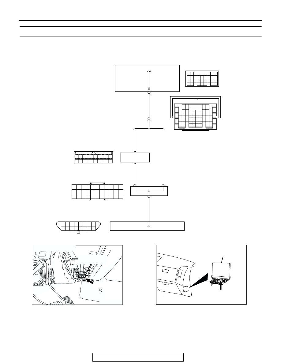
INSPECTION PROCEDURE 2: Scan Tool Communication with PCM Is Not Possible.

RED

-

WHITE

RV METER

RED

-WHITE

RED

-

WHITE

GREEN-

ORANGE

AK201153

GREEN-

ORANGE

28

74

7

DATA LINK
CONNECTOR

30

32

31

5

15

5

8

10

13

11

14

16 17

1 2 3 4

18

9

12

19 20

6 7

15

D-08

(MU801585)

POWERTRAIN
CONTROL
MODULE (PCM)

WITH
RV METER

WITHOUT
RV METER

9

6

10

17

18

29

2

3 4

7 8

19 20

30 31

12

11

24

33 34 35

21

32

27

26

36 37

28

38

25

13

15

14

16

23

22

1

5

E-111

1

10

9

2

11

3

12

4

13

5

14

6

15

7

16

8

D-118

Data Link Connector Circuit

1

12

23 24 25 26

2

13

3

14

4

15

5

16

6

17

7

18

8

19

9

20 21 22

27 28 29 30 31 32 33

10 11

D-29

61
656667686970 717273
74757677787980 8182
8384

858687

8889

62

6364

D-134

(MU803804)

AK200976

DATA LINK
CONNECTOR

AB

D-118(B)

CONNECTOR: D-118

AK201038

CONNECTOR: D-134

AD

PCM

D-134(GR)

TSB Revision

SYMPTOM PROCEDURES

13Ad-6

.

CIRCUIT OPERATION

• A diagnostic output is made from the PCM (termi-

nal No. 74) to the diagnostic output terminal (ter-
minal No. 7) of the data link connector.

.

COMMENT

• No power supply to PCM.

• Defective ground circuit of PCM.

• Defective PCM.

• Improper communication line between PCM and 

scan tool.

.

TROUBLESHOOTING HINTS (The most likely 
causes for this case: ) 

• Malfunction of PCM power supply circuit. 

• Malfunction of the PCM. 

• Open circuit between PCM and data link connec-

tor. 

DIAGNOSIS

STEP 1. Check harness connector D-134 at PCM for 
damage.
Q: Is the harness connector in good condition?

YES :  Go to Step 2.
NO :  Repair or replace it. Refer to GROUP 00E, Harness 

Connector Inspection 

P.00E-2

. Then confirm that the 

malfunction symptom is eliminated.

AK201043

E-111

AB

CONNECTOR: E-111

AK201042AC

CONNECTOR: D-08

D-08

AK201044

D-29

AB

CONNECTOR: D-29

AK201166

61

62

63

64

65

66

67

68

69

70

71

76

77

78

79

85

86

87

80

72

73

74

75

81

82

83

84

88

89

CONNECTOR: D-134

AB

PCM

D-134(GR)

HARNESS CONNECTOR: 
COMPONENT SIDE

TSB Revision

SYMPTOM PROCEDURES

13Ad-7

STEP 2. Check for open circuit, short circuit to ground and 
harness damage between data link connector D-118 
(terminal No. 7) and PCM connector D-134 (terminal No. 
74).
NOTE: Check harness after checking intermediate connectors 
D-210, D-08 and E-111. If intermediate connector D-210, D-08 
and E-111 are damaged, repair or replace them. Refer to 
GROUP 00E, Harness Connector Inspection 

P.00E-2

. Then 

check that the malfunction is eliminated.
Q: Is the harness wire in good condition?

YES :  Refer to INSPECTION PROCEDURE 28 

− Power 

Supply System and Ignition Switch-IG System 

P.13Ad-75

.

NO :  Repair it. Then confirm that the malfunction symptom 

is eliminated.

AK201285

1 2 3 4 5 6

12

11

10

1516

14

13

9

7 8

AB

D-118(B)

CONNECTOR: D-118

HARNESS CONNECTOR: 
COMPONENT SIDE

AK201166

61

62

63

64

65

66

67

68

69

70

71

76

77

78

79

85

86

87

80

72

73

74

75

81

82

83

84

88

89

CONNECTOR: D-134

AB

PCM

D-134(GR)

HARNESS CONNECTOR: 
COMPONENT SIDE

TSB Revision

SYMPTOM PROCEDURES

13Ad-8

INSPECTION PROCEDURE 3: The Malfunction Indicator Lamp (SERVICE ENGINE SOON or Check 
Engine Lamp) Does Not Illuminate Right after the Ignition Switch Is Turned to the "ON" Position.

AK201154

RED-

WHITE

RED-

WHITE

BLA

CK-

WHITE

BLUE-

BLA

CK

14

7

38

37 38

39

40

43

41 42

44

47

45 46

32

31

33 34 35 36

D-04

62

1

2

2

R

IG2

ST

LOCK

ACC

IG1

IGNITION
SWITCH

MALFUNCTION INDICATOR LAMP

SERVICE ENGINE SOON 
OR CHECK ENGINE LAMP

POWERTRAIN
CONTROL
MODULE (PCM)

3

4 5 6

1 2

D-204

5 6

1
3

2

4

D-208

MU801331

9

6

10

17

18

29

2

3 4

7 8

19 20

30 31

12

11

24

33 34 35

21

32

27

26

36 37

28

38

25

13

15

14

16

23

22

1

5

E-111

53 54 55 56 57 58

59

60

63

61 62

64

67

65 66

52

51

D-03

13

3

5

7

12

9

1

6

8

11

10

2

4

D-210

(MU801860)

Malfunction Indicator Lamp (SERVICE ENGINE SOON or Check Engine Lamp) Circuit

(

)

1

2

3

5

6 7 8 9

4

20

21 22

232425

2627

10111213

14 15

16 1718

19

D-132

(MU803802)

6

10A


Content   ..  737  738  739  740   ..