Mitsubishi Montero (2002-2004). Manual - part 673


  Index      Mitsubishi     Mitsubishi Montero - service repair manual 2002-2004 year


Search            


Content   ..  671  672  673  674   ..


Mitsubishi Montero (2002-2004). Manual - part 673


TSB Revision

DIAGNOSTIC TROUBLE CODE PROCEDURES

13Ac-389

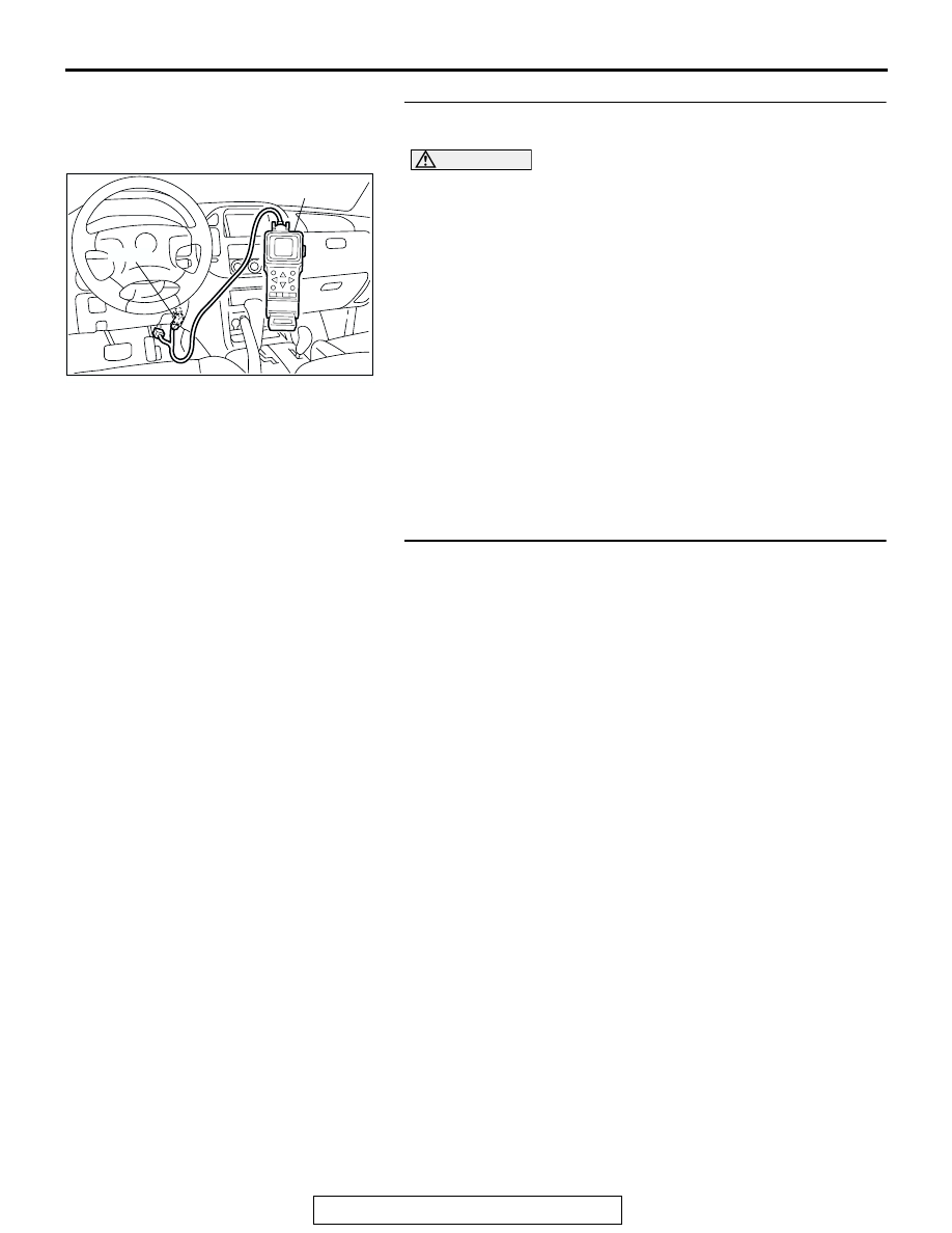
STEP 2. Using scan tool MB991502, check data list item 95: 
Manifold Differential Pressure Sensor.

CAUTION

To prevent damage to scan tool MB991502, always turn the 
ignition switch to the "LOCK" (OFF) position before con-
necting or disconnecting scan tool MB991502.
(1) Connect scan tool MB991502 to the data link connector.
(2) Start the engine and run at idle.
(3) Set scan tool MB991502 to the data reading mode for item 

95, Manifold Differential Pressure Sensor.

(4) Warm up the engine to normal operating temperature: 80

°C 

to 95

°C (176°F to 203°F).

• Should be between 20.6 − 34.0 kPa (6.1 − 10.0 in.Hg) at 

engine idling.

(5) Turn the ignition switch to the "LOCK" (OFF) position.
Q: Is the sensor operating properly?

YES : Clean the EGR valve and EGR passage. Then go to 

Step 3.

NO :  Refer to DTC P1400 

− Manifold Differential Pressure 

Sensor Circuit Malfunction 

P.13Ac-557

.

STEP 3. Test the OBD-II drive cycle.
(1) Carry out a test drive with the drive cycle pattern. Refer to 

GROUP 13A, Procedure 5 

− Exhaust Gas Recirculation 

(EGR) System Monitor 

P.13Ab-2

.

(2) Check the diagnostic trouble code (DTC).
Q: Is DTC P0401 set?

YES : Retry the troubleshooting.
NO :  The inspection is complete.

ACX01539

16-PIN

MB991502

AC

TSB Revision

DIAGNOSTIC TROUBLE CODE PROCEDURES

13Ac-390

DTC P0403: Exhaust Gas Reculation Control Circuit

WHITE-

BLA

CK

WHITE-

BLA

CK

RED

GREEN-BLA

CK

RED

RED

GREEN-RED

BLUE-ORANGE

BLA

CK-YELLO

W

AK201148

MFI RELAY

BATTERY

3

2

1

4

3 4

1 2

B-22X

B-56

(MU802056)

2

5

3

12

19

26

1

3

4

6

EGR
VALVE

POWERTRAIN
CONTROL
MODULE (PCM)

EGR Valve Circuit

1

2 3

4

5 6

1

2

3

5

6 7 8 9

4

20

21 22

232425

2627

10111213

14 15

16 1718

19

D-132

(MU803802)

TSB Revision

DIAGNOSTIC TROUBLE CODE PROCEDURES

13Ac-391

.

CIRCUIT OPERATION

• The EGR valve power is supplied from the MFI 

relay (terminal No. 1).

• The PCM (terminals No. 3, No. 12, No. 19, No. 

26) drives the stepper motor by sequentially turn-
ing "ON" the power transistors in the PCM and 
providing ground to the idle air control motor (ter-
minal No. 1, No. 3, No. 4, No. 6).

.

TECHNICAL DESCRIPTION

• To judge if there is open circuit in the EGR valve 

(stepper motor) drive circuit, PCM measure the 
surge voltage of the EGR valve motor coil.

.

DTC SET CONDITIONS

Check Conditions

• Ignition switch: "OFF" to "ON".

• EGR valve is in operration after the ensgine start-

ing process is complete. (While EGR valve is ini-
tialized.)

Judgment Criteria

• The EGR valve motor coil surge voltage (battery 

positive voltage + 2 volts) is not detected for 3 
sconds.

• The PCM monitor for this condition once during 

the drive cycle.

.

TROUBLESHOOTING HINTS (The most likely 
causes for this code to be set are: )

• EGR valve (stepper motor) failed.

• Open or shorted EGR valve (stepper motor) cir-

cuit, or loose connector.

• PCM failed.

AK200966

EGR 
VALVE

AB

B-56(GR)

CONNECTOR: B-56

AK201038

CONNECTOR: D-132

AB

PCM

D-132(GR)

AK201039

MFI RELAY

B-22X

AB

CONNECTOR: B-22X

TSB Revision

DIAGNOSTIC TROUBLE CODE PROCEDURES

13Ac-392

DIAGNOSIS

Required Special Tools:

• MB991502: Scan Tool (MUT-II)

• MB991658: Test harness Set

STEP 1. Check connector B-56 at EGR valve for damage.
Q: Is the connector in good condition?

YES : Go to Step 2.
NO :  Repair or replace it. Refer to GROUP 00E, Harness 

Connector Inspection 

P.00E-2

. Then go to Step 12.

STEP 2. Measure the EGR valve motor coil resistance.
(1) Disconnect the EGR valve connector B-56.

(2) Measure the resistance between EGR valve connector 

terminal No. 2 and either terminal No. 1 or terminal No. 3.

Standard value: 20 

 24 ohms [at 20°C (68°F)]

(3) Measure the resistance between EGR valve connector 

terminal No. 5 and either terminal No. 4 or terminal No. 6.

Standard value: 20 

 24 ohms [at 20°C (68°F)]

Q: Is the resistance normal?

YES : Go to Step 3.
NO :  Replace the EGR valve. Then go to Step 12.

AK200967

1

2

3

4

5

6

AB

HARNESS 
CONNECTOR: 
COMPONENT SIDE

B-56(GR)

CONNECTOR: B-56

AK200967

1

2

3

4

5

6

AB

HARNESS 
CONNECTOR: 
COMPONENT SIDE

B-56(GR)

CONNECTOR: B-56

1

2 3

4

5 6

1

2 3

4

5 6

AK201418


Content   ..  671  672  673  674   ..