Mitsubishi Montero (2002-2004). Manual - part 674
TSB Revision
DIAGNOSTIC TROUBLE CODE PROCEDURES
13Ac-393
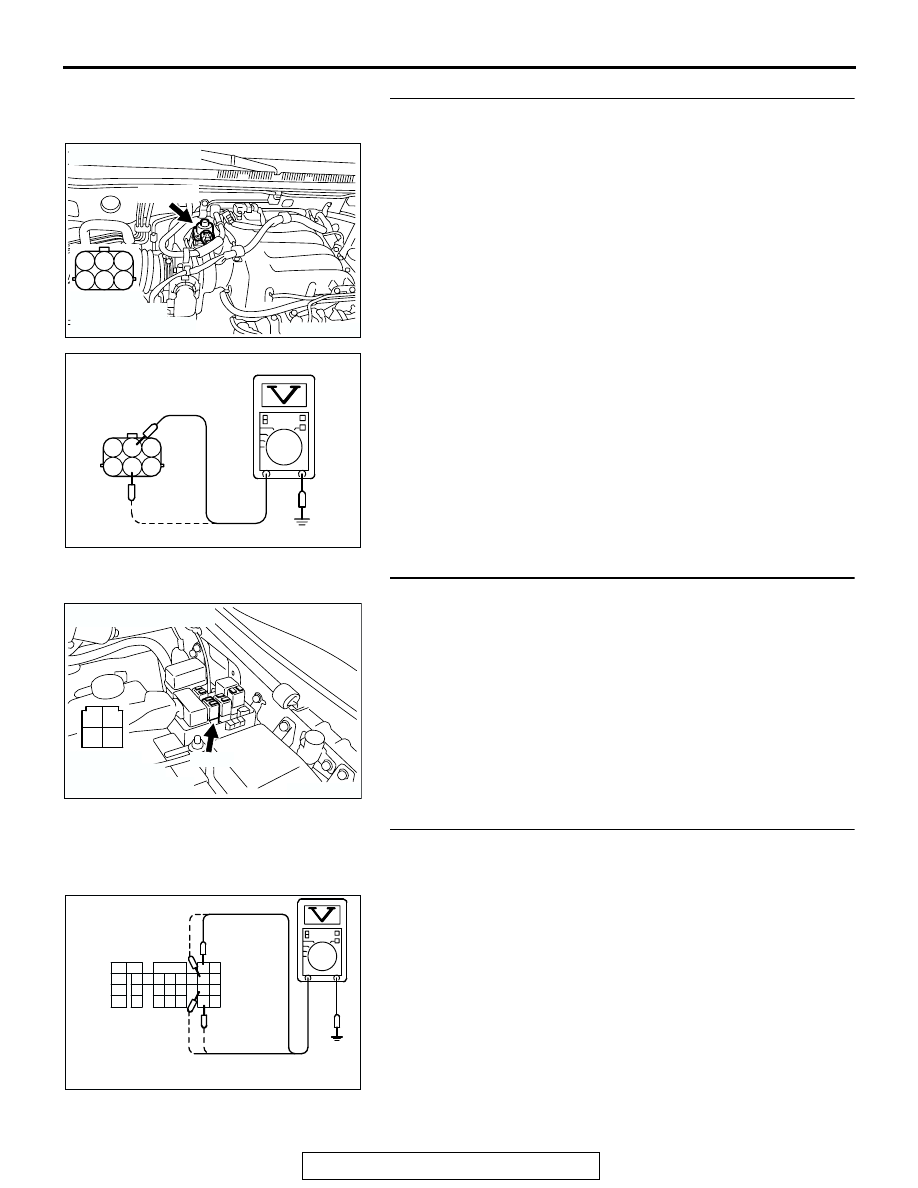
STEP 3. Measure the power supply voltage at EGR valve
motor harness side connector B-56.
(1) Disconnect the connector B-56 and measure at the harness
side.
(2) Turn the ignition switch to the "ON" position.
(3) Measure the voltage between terminal No. 2, No. 5 and
ground.
• Voltage should be battery positive voltage.
(4) Turn the ignition switch to the "LOCK" (OFF) position.
Q: Is battery positive voltage (approximately 12 volts)
present?
YES : Go to Step 5.
NO : Go to Step 4.
STEP 4. Check connector B-22X at MFI relay for damage.
Q: Is the connector in good condition?
YES : Repair harness wire between MFI relay connector B-
22X (terminal No. 1) and idle air control motor
connector B-56 (terminal No. 2, No. 5) because of
open circuit or short circuit to ground. Then go to Step
12.
NO : Repair or replace it. Refer to GROUP 00E, Harness
Connector Inspection
. Then go to Step 12.
STEP 5. Measure the power supply voltage at PCM
connector D-132 by backprobing.
(1) Do not disconnect the connector D-132.
(2) Measure the voltage between terminal (No. 3, No. 12, No.
19, No. 26) and ground by backprobing.
• The voltage is 1volt or lower for approximately 3 sec-
onds, then changes to the battery positive voltage when
the Ignition switch is turned from the "LOCK" (OFF)
position to the "ON" position.
(3) Turn the ignition switch to the "LOCK" (OFF) position.
Q: Is the voltage normal?
YES : Go to Step 8.
NO : Go to Step 6.
AK200967
1
2
3
4
5
6
AB
HARNESS
CONNECTOR:
COMPONENT SIDE
B-56(GR)
CONNECTOR: B-56
1
2
3
4
5
6
AK201419
B-56 HARNESS
CONNECTOR:
CONPONENT SIDE
AB
AK200951
2 1
3
4
B-22X
AB
CONNECTOR: B-22X
HARNESS
CONNECTOR:
COMPONENT SIDE
1
2
3
5
6 7 8 9
4
20
21 22
232425
2627
10111213
14 15
16 1718
19
AK201420
D-132 HARNESS
CONNECTOR:
HARNESS SIDE
AB