Mitsubishi Montero (2002-2004). Manual - part 667


  Index      Mitsubishi     Mitsubishi Montero - service repair manual 2002-2004 year


Search            


Content   ..  665  666  667  668   ..


Mitsubishi Montero (2002-2004). Manual - part 667


TSB Revision

DIAGNOSTIC TROUBLE CODE PROCEDURES

13Ac-365

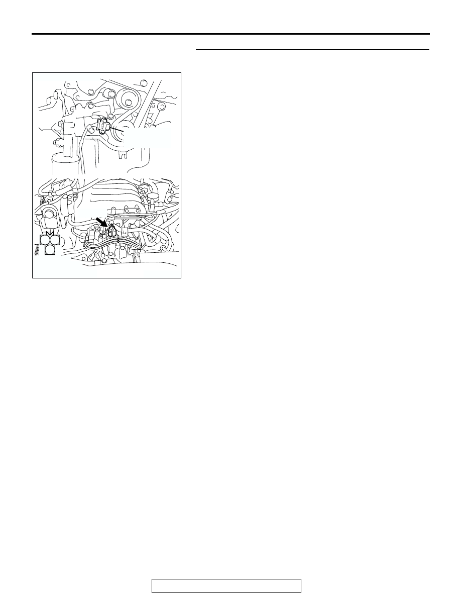
STEP 5. Check connector B-36 at the crankshaft position 
sensor for damage.
Q: Is the connector in good condition?

YES : Go to Step 6.
NO :  Repair or replace it. Refer to GROUP 00E, Harness 

Connector Inspection 

P.00E-2

. Then go to Step 21.

AK200962

1

2

3

AB

CONNECTOR: B-36

B-36(B)

CRANKSHAFT
POSITION
SENSOR

HARNESS 
CONNECTOR: 
COMPONENT SIDE

TSB Revision

DIAGNOSTIC TROUBLE CODE PROCEDURES

13Ac-366

STEP 6. Measure the sensor supply voltage at crankshaft 
position sensor harness side connector B-36.
(1) Disconnect the connector B-36 and measure at the harness 

side.

(2) Turn the ignition switch to the "ON" position.

(3) Measure the voltage between terminal No. 2 and ground.

• Voltage should be between 4.8 and 5.2 volts.

(4) Turn the ignition switch to the "LOCK" (OFF) position.
Q: Is the measured voltage between 4.8 and 5.2 volts?

YES : Go to Step 11.
NO :  Go to Step 7.

AK200962

1

2

3

AB

CONNECTOR: B-36

B-36(B)

CRANKSHAFT
POSITION
SENSOR

HARNESS 
CONNECTOR: 
COMPONENT SIDE

AKX01416 AK

2 1

3

B-36 HERNESS 
CONNECTOR: 
COMPONENT SIDE

TSB Revision

DIAGNOSTIC TROUBLE CODE PROCEDURES

13Ac-367

STEP 7. Measure the sensor supply voltage at PCM 
connector D-134 by backprobing.
(1) Do not disconnect the PCM connector D-134.
(2) Disconnect the crankshaft position sensor connector B-36.
(3) Turn the ignition switch to the "ON" position.

(4) Measure the voltage between terminal No. 70 and ground 

by backprobing.

• Voltage should be between 4.8 and 5.2 volts.

(5) Turn the ignition switch to the "LOCK" (OFF) position.
Q: Is the measured voltage between 4.8 and 5.2 volts?

YES : Go to Step 8.
NO :  Go to Step 9.

STEP 8. Check connector D-134 at PCM for damage.
Q: Is the connector in good condition?

YES : Repair it because of open circuit between crankshaft 

position sensor connector B-36 (terminal No. 2) and 
PCM connector D-134 (terminal No. 70). Then go to 
Step 21.

NO :  Repair or replace it. Refer to GROUP 00E, Harness 

Connector Inspection 

P.00E-2

. Then go to Step 21.

AK201166

61

62

63

64

65

66

67

68

69

70

71

76

77

78

79

85

86

87

80

72

73

74

75

81

82

83

84

88

89

CONNECTOR: D-134

AB

PCM

D-134(GR)

HARNESS CONNECTOR: 
COMPONENT SIDE

AK201416

61
656667686970 717273
74757677787980 8182
8384

858687

8889

62

6364

AB

D-134 HARNESS 
CONNECTOR: 
HARNESS SIDE

AK201166

61

62

63

64

65

66

67

68

69

70

71

76

77

78

79

85

86

87

80

72

73

74

75

81

82

83

84

88

89

CONNECTOR: D-134

AB

PCM

D-134(GR)

HARNESS CONNECTOR: 
COMPONENT SIDE

TSB Revision

DIAGNOSTIC TROUBLE CODE PROCEDURES

13Ac-368

STEP 9. Check connector D-134 at PCM for damage.
Q: Is the connector in good condition?

YES : Go to Step 10.
NO :  Repair or replace it. Refer to GROUP 00E, Harness 

Connector Inspection 

P.00E-2

. Then go to Step 21.

AK201166

61

62

63

64

65

66

67

68

69

70

71

76

77

78

79

85

86

87

80

72

73

74

75

81

82

83

84

88

89

CONNECTOR: D-134

AB

PCM

D-134(GR)

HARNESS CONNECTOR: 
COMPONENT SIDE


Content   ..  665  666  667  668   ..