Mitsubishi Montero (2002-2004). Manual - part 515
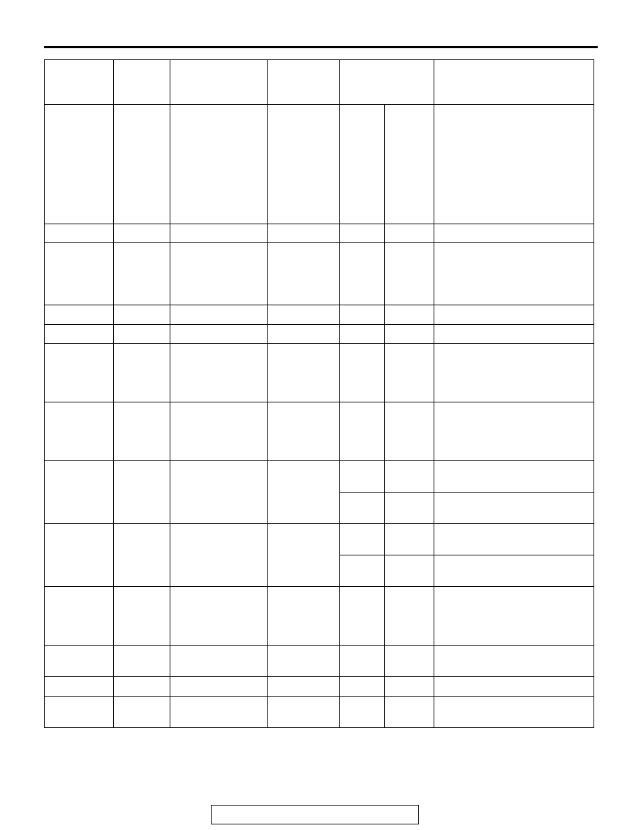
RV METER
TSB Revision
CHASSIS ELECTRICAL
54A-231
15
Input/
output
K (engine K-line
signal)
Hi: Battery
positive
voltage
Lo: 0
− 1
Open
circuit
Short
circuit
•Drive range is not displayed.
•Connection, communication
error.
•Impossible to communicate
between power train control
module and the scan tool.
•Values of drive information
display are abnormal.
16
− 18
−
−
−
−
−
−
19
Input/
output
M-BUSY (A/C)
Hi: 5
Lo: 0
− 1
Open
circuit
Short
circuit
•Air-conditioner information
screen is not displayed.
•Ambient temperature is not
indicated.
20
−
SHIELD-GND
−
−
−
−
21
− 22
−
−
−
−
−
−
23
Input EX-TEMP
(ambient
temperature
sensor signal)
0
− 5
Open
circuit
Short
circuit
Ambient temperature is not
displayed. (MANUAL A/C)
24
Input
ILL + (lighting
switch)
Hi: Battery
positive
voltage
Lo: 0
− 1
Open
circuit
Short
circuit
Not lighted.
25
Input
ACC (ACC power
supply)
Battery
positive
voltage
Open
circuit
−
Screen is not displayed. All
operations are not possible.
−
Short
circuit
Multi-use fuse is blown.
26
Input
+B
Battery
positive
voltage
Open
circuit
−
Screen is not displayed. All
operations are not possible.
−
Short
circuit
Multi-use fuse is blown.
27
Input
VSS (Vehicle
speed pulse
signal)
Hi: Battery
positive
voltage
Lo: 0
− 1
Open
circuit
Short
circuit
Abnormal maintenance
screen display
28
−
GND (earth)
−
Open
circuit
−
Screen is not displayed.
29
− 30
−
−
−
−
−
−
31
−
GND
− TEMP
−
Open
circuit
Short
circuit
Ambient temperature is not
displayed. (MANUAL A/C)
TERMINAL
NO.
INPUT/
OUTPUT
SIGNAL
SYMBOL
TERMINAL
VOLTAGE
(V)
HARNESS
DISCREPANCY
FAILURE SYMPTOM DUE
TO HARNESS
DISCREPANCY