Mitsubishi Montero (2002-2004). Manual - part 514


  Index      Mitsubishi     Mitsubishi Montero - service repair manual 2002-2004 year


Search            


Content   ..  512  513  514  515   ..


Mitsubishi Montero (2002-2004). Manual - part 514


RV METER

TSB Revision

CHASSIS ELECTRICAL

54A-227

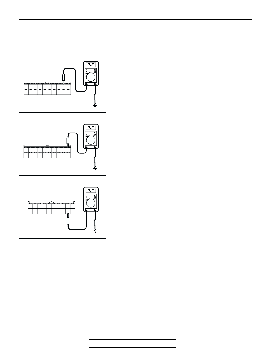
STEP 2. Check the RV meter and A/C-ECU circuit by 
backprobing. 
(1) Do not disconnect RV meter connector D-08.
(2) ignition switch "ACC" position.
(3) Measure the voltage (waveform) between terminal 9 and 

ground using an oscilloscope by backprobing.

(4) Measure the voltage (waveform) between terminal 10 and 

ground by backprobing.

(5) Measure the voltage (waveform) between terminal 19 and 

ground by backprobing.

Q: Is the measured voltage Hi = 4 to 5 volts and Lo = 0 to 1 

volt? 
YES : 
Replace the RV meter display.
No :  Go to Step 5.

AC204738

20

19

18

17

7

6

15

14

4

3

11 12 13

5

1

9 10

2

16

8

AC204738 DV

HARNESS SIDE: D-08

AC204738 DW

HARNESS SIDE: D-08

20

19

18

17

7

6

15

14

4

3

11 12 13

5

1

9 10

2

16

8

AC204738 DX

HARNESS SIDE: D-08

20

19

18

17

7

6

15

14

4

3

11 12 13

5

1

9 10

2

16

8

RV METER

TSB Revision

CHASSIS ELECTRICAL

54A-228

STEP 3. Check the harness wires between RV meter 
connector D-08 (terminal 9 and 10 and 19) and A/C-ECU 
connector D-23 (terminal 16 and 17 and 6).
Q: Are harness wires between RV meter connector D-08 

(terminal 9 and 10 and 19) and A/C-ECU connector D-23 
(terminal 16 and 17 and 6) in good condition?
YES : 
There is no action to be taken.
NO :  Repair or replace them. Refer to GROUP 00E, 

Harness Connector Inspection 

P.00E-2

.

STEP 4. Check the A/C-ECU.

CAUTION

To Prevent to damage to scan toll MB991502, always turn 
the ignition switch to "LOCK" (OFF) position before con-
necting or disconnecting scan tool MB991502.
(1) Connect scan tool MB991502 to the data link connector.
(2) Turn the ignition switch to "ON" position.
(3) Read the A/C diagnostic trouble code.
Q: Is the A/C diagnostic trouble code set? 

YES : Carry out troubleshooting of the A/C.
NO :  There is no action to be taken.

AC204188

D-08(B)

1

3

4

2

12

1413

11

6

7

8

10 9

18

19

20

16

17

5

15

AC204188

CONNECTORS: D-08, D-23

BU

HARNESS SIDE

HARNESS SIDE

D-08(B)

D-23(B)

D-23(B)

1

3

4

2

12

1413

11

6

7

8

10 9

18

19

20

16

17

5

15

ACX01539

16-pin

MB991502

AI

RV METER

TSB Revision

CHASSIS ELECTRICAL

54A-229

STEP 5. Check the A/C-ECU by backprobing.
(1) Do not disconnect A/C-ECU connector D-23.
(2) ignition switch "ACC" position.
(3) Measure the voltage (waveform) between terminal 6 and 

ground using an oscilloscope by backprobing.

(4) Measure the voltage (waveform) between terminal 16 and 

ground by backprobing.

(5) Measure the voltage (waveform) between terminal 17 and 

ground by backprobing.

Q: Is the measured voltage Hi = 4 to 5 volts and Lo = 0 to 1 

volt?
YES : 
Go to Step 6.
NO :  Replace the A/C-ECU.

STEP 6. Recheck for malfunction.
Q: Is a malfunction eliminated?

YES : If no malfunctions are not found in all steps, an 

intermittent malfunction is suspected. Refer to 
GROUP 00, How to Use Troubleshooting/Inspection 
Service Points 

− How to Cope with Intermittent 

Malfunction 

P.00-6

.

NO :  Replace the RV meter.

AC204738 DY

HARNESS SIDE: D-23

20

19

18

17

7

6

15

14

4

3

11 12 13

5

1

9 10

2

16

8

AC204738 DZ

HARNESS SIDE: D-23

20

19

18

17

7

6

15

14

4

3

11 12 13

5

1

9 10

2

16

8

AC204738 EA

HARNESS SIDE: D-23

20

19

18

17

7

6

15

14

4

3

11 12 13

5

1

9 10

2

16

8

RV METER

TSB Revision

CHASSIS ELECTRICAL

54A-230

CHECK AT RV METER TERMINAL

M1543007600241

ACX02122 AB

D-07

D-08

TERMINAL 
NO.

INPUT/
OUTPUT

SIGNAL
SYMBOL

TERMINAL 
VOLTAGE 
(V)

HARNESS 
DISCREPANCY

FAILURE SYMPTOM DUE 
TO HARNESS 
DISCREPANCY

− 4

5

Input

ISOK (MUT-II 
data signal)

Hi: Battery 
positive 
voltage
Lo: 0 

− 1

Open 
circuit

Short 
circuit

Impossible to communicate 
between power train control 
module and the scan tool by 
the scan tool

6

Input/
output

DATA (ETACS 
SWS data signal)

Hi: Battery 
positive 
voltage 
Lo: 0 

− 1

Open 
circuit

Short 
circuit

•Switch operating sound 

(buzzer) cannot be heard.
•Daytime/night display mode 

interlocked with tail lamp is 
not switched.
•Lamp (illuminated button) is 

not lighted

− 8

9

Input/
output

M-DATA (A/C) 
(M-BUS data 
signal)

Hi: 4 

− 5

Lo: 0 

− 1

Open 
circuit

Short 
circuit

•Air-conditioner information 

screen is not displayed.
•Ambient temperature is not 

indicated.

10

Input/
output

M-CLOCK (A/C) 
(M-BUS clock 
signal)

Hi: 4 

− 5

Lo: 0 

− 1

Open 
circuit 

Short 
circuit

•Air-conditioner information 

screen is not displayed.
•Ambient temperature is not 

indicated.

11 

− 14


Content   ..  512  513  514  515   ..