Mitsubishi Montero (2002-2004). Manual - part 475


  Index      Mitsubishi     Mitsubishi Montero - service repair manual 2002-2004 year


Search            


Content   ..  473  474  475  476   ..


Mitsubishi Montero (2002-2004). Manual - part 475


HEADLIGHT, FRONT SIDE MARKER LIGHT AND POSITION LIGHT ASSEMBLY

TSB Revision

CHASSIS ELECTRICAL

54A-71

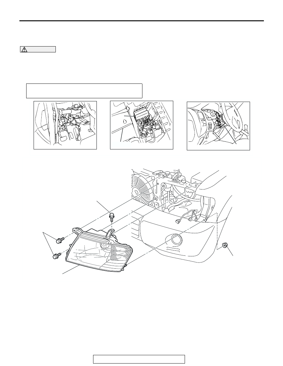
HEADLIGHT AND FRONT COMBINATION LIGHT

REMOVAL AND INSTALLATION

M1542002700239

WARNING

Before removal of the air bag module, refer to GROUP 52B, SRS Service Precautions and 
Air Bag Module and Clock Spring 

P.52Ba-18

.

When removing and installing the steering wheel, do not let it bump against the air bag 
module.

Post-installation operation
• Headlight aiming adjustment (Refer to 

P.54A-68

.)

ACX01803AC

1

2

3

BATTERY

AC204111AB

4.9 ± 0.7 N

·

m

43 ± 6 in-lb

4.9 ± 0.7 N

·

m

43 ± 6 in-lb

4.9 ± 0.7 N

·

m

43 ± 6 in-lb

4

1.

ETACS-ECU

2.

FRONT-ECU

3.

COLUMN SWITCH (REFER TO 
GROUP 37, STEERING WHEEL 
AND SHAFT 

P.37A-23

.)

HEADLIGHT REMOVAL STEPS

RADIATOR GRILL (REFER TO 
GROUP 51, FRONT BUMPER 

P.51-3

.)

<<A>>

4.

HEADLIGHT ASSEMBLY

FOG LIGHT

TSB Revision

CHASSIS ELECTRICAL

54A-72

REMOVAL SERVICE POINT

.

<<A>> HEADLIGHT ASSEMBLY REMOVAL
Remove the headlight mounting nut to remove the headlight. 
The nut is found at the inner side of the vehicle among the nuts 
that appear when the splash shield is removed at the front side. 

FOG LIGHT

FOG LIGHT DIAGNOSIS

M1542010500252

The fog lights are controlled by the Simplified Wiring 
System (SWS). For troubleshooting, refer to GROUP 
54B, SWS Diagnosis 

P.54Ba-6

.

AC204789AB

5.0 ± 1.0 N

·

m

44 ± 9 in-lb

5

6

DRL-ECU REMOVAL STEPS

5.

DRL-ECU

6.

DRL-ECU BRACKET

ACX00791AB

INSIDE OF 
VEHICLE

FOG LIGHT

TSB Revision

CHASSIS ELECTRICAL

54A-73

ON-VEHICLE SERVICE

FOG LIGHT AIMING

M1542001100331

PRE-AIMING INSTRUCTIONS

1. Inspect for badly rusted or faulty headlight assemblies.
2. These conditions must be corrected before a satisfactory 

adjustment can be made.

3. Inspect tire inflation, and adjust if necessary.
4. If the fuel tank is not full, place a weight in luggage room of 

vehicle to simulate weight of a full tank [3 kg (6.5 pounds) 
per gallon.]

5. There should be no other load in the vehicle other than 

driver or substituted weight of approximately 70 kg (150 
pounds) placed in driver's position.

6. Thoroughly clean fog light lenses.
7. Place the vehicle on a level floor, perpendicular to a flat 

screen 7.62 m (25.0 feet) away from the bulb center-marks 
on the fog light lens.

8. Rock vehicle sideways to allow vehicle to assume its normal 

position.

9. Bounce the front suspension through three (3) oscillations 

by applying the body weight to hood or bumper.

10.Measure the center of the fog lights as shown in the 

illustration.

11.Four lines of adhesive tape (or equivalent markings) are 

required on screen or wall:

(1) Position a vertical tape or mark so that it is aligned with 

the vehicle center line.

(2) Measure the distance from the center-marks on the fog 

light lens to the floor. Transfer the measurement to the 
screen. Horizontal tape or mark on the screen is for 
reference of vertical adjustment.

(3) Measure the distance from the center line of the vehicle 

to the center of each fog light. Transfer the measurement 
to the screen. Vertical tape or mark on the screen with 
reference to the center line of each fog light bulb.

AC204112 AB

CENTER OF 
THE LIGHT

AC005167

SCREEN

(1)

(2)

(3)

(3)

FOG LIGHT CENTER

VEHICLE CENTER  
LINE

7.62m (25.0 ft)

AD

FOG LIGHT

TSB Revision

CHASSIS ELECTRICAL

54A-74

FOG LIGHT ADJUSTMENT

1. Check if the beam shining onto the screen is at the standard 

value.

Standard value:

(Vertical direction): Top of the hot zone should be 

101 mm (4.0 inches) below the fog light center 
(equivalent to the fog light beam angle of 0.76

°). 

(Horizontal direction): Parallel to direction of vehicle 

travel

Limit:

(Vertical direction): Top of the hot zone should be 

152 mm (6.0 inches) below the fog light center 
(equivalent to the fog light beam angle of 1.14

°).

2. If the value is outside the standard value range, adjust using 

the adjusting screw.
NOTE: The horizontal direction is non-adjustable. If devia-
tion of the light beam axis exceeds the standard value, 
check that the mounting location or some other points are 
not faulty.

AC100547

HEIGHT OF FOG

LIGHT CENTER

VERTICAL CENTER LINE 

AHEAD OF FOG LIGHT

UPPER MOST LEVEL 

OF HOT ZONE

HOT ZONE

mm (in)

AB

152 (6.0)

101 (4.0)

598 (23.5)

598 (23.5)

AC204113 AB

AC204113

ADJUSTING SCREW


Content   ..  473  474  475  476   ..