Mitsubishi Montero (2002-2004). Manual - part 435
POWER STEERING GEAR BOX ASSEMBLY
TSB Revision
POWER STEERING
37A-27
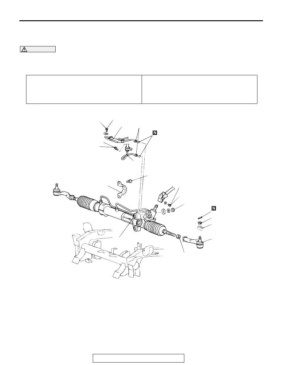
POWER STEERING GEAR BOX ASSEMBLY
REMOVAL AND INSTALLATION
M1372003900235
WARNING
Before removing the steering gear box, refer to GROUP 52B. Center the front wheels and
remove the ignition key. Failure to do so may damage the SRS clock spring and render the
SRS system inoperative, risking serious injury.
Required Special Tool:
• MB991897: Ball Joint Remover
Pre-removal Operation
Power Steering Fluid Draining (Refer to
.)
Post-installation Operation
• Fill power steering fluid and bleed air (Refer to
.)
• Check the Dust Cover for Cracks or Damage by Pushing
it with Your Finger.
• Check the steering angle (Refer to
AC000760
71
±
7 N
·
m
53
±
5 ft-lb
18
±
2 N
·
m
13
±
2 ft-lb
39
±
5 N
·
m
29
±
3 ft-lb
69
±
10 N
·
m
51
±
7 ft-lb
69
±
10 N
·
m
51
±
7 ft-lb
12
±
2 N
·
m
107
±
17 in-lb
12
±
2 N
·
m
107
±
17 in-lb
2
2
6
3
4
7
8
5
1
AB
15
±
3 N
·
m
11
±
2 ft-lb
REMOVAL STEPS
•
REMOVAL OF UNDER COVER
<<A>>
1. TIE ROD END AND KNUCKLE
CONNECTION
2. BOLT
>>B<<
3. PRESSURE HOSE ASSEMBLY
>>B<<
4. RETURN TUBE
>>A<<
5. TIE ROD END (LH)
<<B>>
•
INSTALLATION OF DIFFERENTIAL
MOUNT BRACKET (LH)
6. STEERING SHAFT ASSEMBLY AND
GEAR BOX CONNECTING BOLT
7. GEAR BOX CLAMP
<<C>>
8. GEAR BOX ASSEMBLY
REMOVAL STEPS (Continued)