Mitsubishi Montero (2002-2004). Manual - part 434
STEERING WHEEL AND SHAFT ASSEMBLY
TSB Revision
POWER STEERING
37A-23
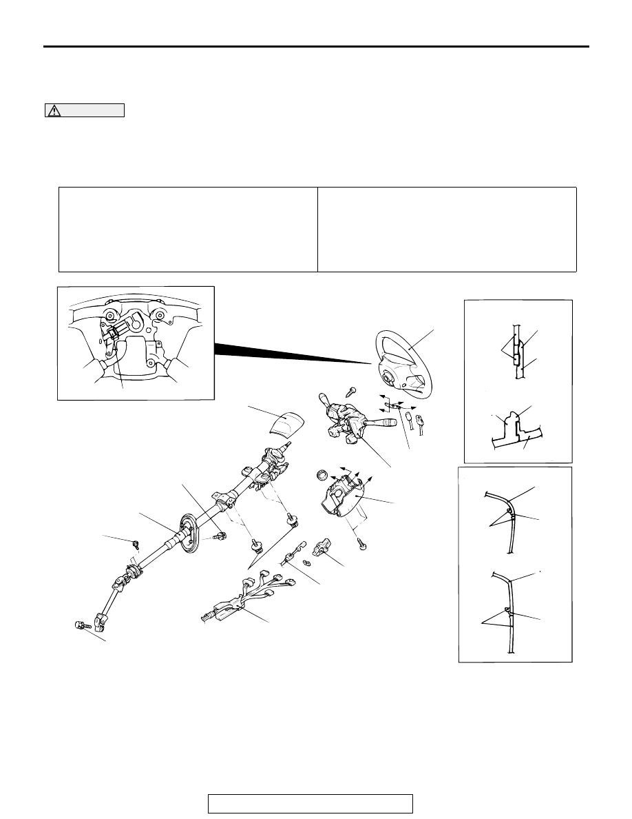
STEERING WHEEL AND SHAFT ASSEMBLY
REMOVAL AND INSTALLATION
M1372002600219
WARNING
•
Before removing the air bag module, refer to GROUP 52B, Service Precautions and Air
Bag Module and Clock Spring
.
•
When removing and installing the steering wheel, do not let it bump against the air bag
module.
Pre-removal Operation
• Removal of Air Cleaner, Air Intake Hose and Intake Air
Duct (Refer to GROUP 15, Air Cleaner
• Lower Panel Removal (Refer to GROUP 52A, Instrument
.)
Post-installation Operation
• Lower Panel Installation (Refer to GROUP 52A, Instru-
ment Panel Assembly
• Installation of Air Cleaner, Air Intake Hose and Intake Air
Duct (Refer to GROUP 15, Air Cleaner
• Checking Steering Wheel Position with Wheels Straight
Ahead
ACX01135
AB
2
2
2
1
1
A
A
B
B
SECTION A
-
A
SECTION B
-
B
CLAW
CLAW
SECTION C
-
C
SECTION D
-
D
CLAW
CLAW
3
C
C
D
D
5
3
3
4
4
6
7
8
9
13
±
2 N
•
m
115
±
18 in-lb
22
±
4 N
•
m
16
±
3 ft-lb
18
±
2 N
•
m
13
±
2 ft-lb
5.0
±
1.0 N
•
m
44
±
9 in-lb
4
50
±
5 N
•
m
37
±
4 ft-lb
1
REMOVAL STEPS
<<A>>
1. COVER
<<B>>
2. STEERING WHEEL AND AIR BAG
MODULE ASSEMBLY
3. LOWER COLUMN COVER
4. UPPER COLUMN COVER
5. PROTECTOR
6. CLOCK SPRING AND COLUMN
SWITCH ASSEMBLY (REFER TO
GROUP 52B, AIR BAG MODULE
AND CLOCK SPRING
7. COVER
8. KEY INTERLOCK CABLE
REMOVAL STEPS (Continued)