Mitsubishi Montero (2002-2004). Manual - part 417
FRONT SUSPENSION DIAGNOSIS
TSB Revision
FRONT SUSPENSION
33A-3
SYMPTOM CHART
M1332009400212
SYMPTOM PROCEDURES
INSPECTION PROCEDURE 1: Steering Wheel is Heavy, Vibrates or Pulls to One Side
DIAGNOSIS
STEP 1. Check the tires.
Refer to GROUP 31, Diagnosis
Q: Are the tires at normal condition?
YES :
Replace the tires as necessary, then go to
Step 2.
NO :
If out of balance, balance the tires as
necessary. If excessively worn, replace the
tires as necessary and go to Step 5.
STEP 2. Check the wheel alignment.
Q: Is the wheel alignment correct?
YES :
Go to Step 3.
NO :
Adjust it, then go to Step 5.
STEP 3. Check the ball joint.
Q: Is the ball joint in good condition?
YES :
Go to Step 4.
NO :
Replace it, then go to Step 5.
STEP 4. Check the coil spring.
Q: Is the coil spring in good condition?
YES :
Go to Step 5.
NO :
Replace it, then go to Step 5.
STEP 5. Retest the system.
Q: Is the malfunction eliminated?
YES :
The procedure is complete.
NO :
Return to Step 1.
INSPECTION PROCEDURE 2: Excessive Body Rolling
DIAGNOSIS
STEP 1. Check for broken or deteriorated
stabilizer bar.
Q: Is the stabilizer bar in good condition?
YES :
Go to Step 2.
NO :
Replace it, then go to Step 3.
STEP 2. Check for shock absorber damage.
Q: Is the shock absorber in good condition?
YES :
Go to Step 3.
NO :
Replace it, then go to Step 3.
STEP 3. Retest the system.
Q: Is the malfunction eliminated?
YES :
The procedure is complete.
NO :
Return to Step 1.
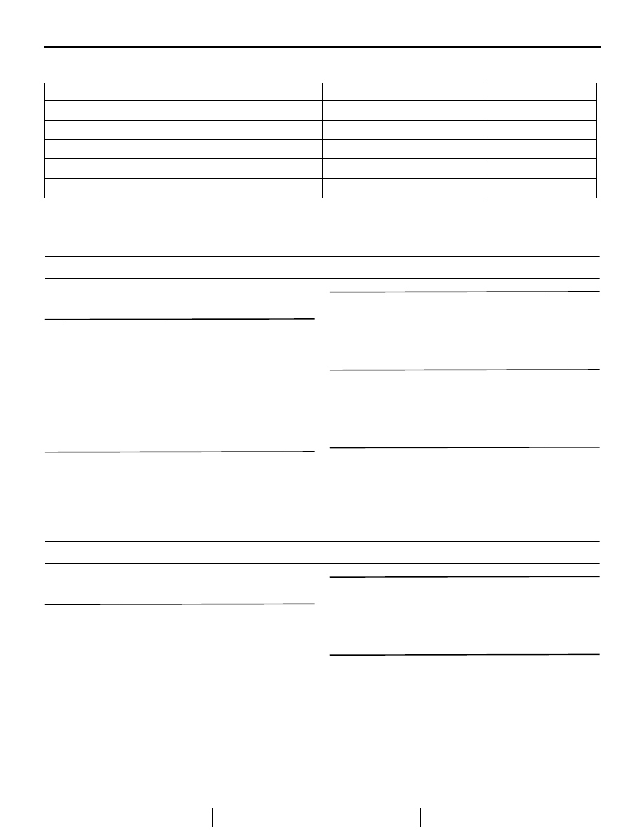
SYMPTOM
INSPECTION PROCEDURE
REFERENCE PAGE
Steering wheel is heavy, vibrates or pulls to one side 1
Excessive body rolling
2
Poor ride
3
Unequal ride height
4
Noise
5