Mitsubishi Montero (2002-2004). Manual - part 416


  Index      Mitsubishi     Mitsubishi Montero - service repair manual 2002-2004 year


Search            


Content   ..  414  415  416  417   ..


Mitsubishi Montero (2002-2004). Manual - part 416


ON-VEHICLE SERVICE

TSB Revision

WHEEL AND TIRE

31-7

ON-VEHICLE SERVICE

TIRE INFLATION PRESSURE CHECK

M1311000900259

NOTE: For information on tire inflation pressure, refer to the 
label attached to the center pillar on the driver's side.

TIRE WEAR CHECK

M1311001000260

Measure the tread depth of the tires.

Minimum limit: 1.6 mm (0.06 inch)

If the remaining tread depth is less than the minimum limit, 
replace the tire.
NOTE: When the tread depth of the tires is reduced to 1.6 mm 
(0.06 inch) or less, wear indicators will appear.
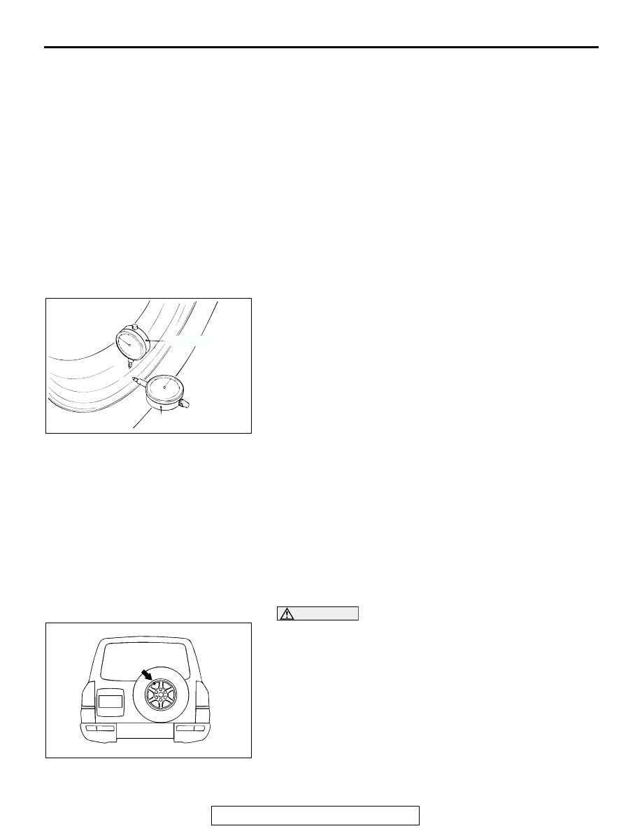
WHEEL RUNOUT CHECK

M1311001100267

Jack up the vehicle so that the wheels are clear of the floor. 
While slowly turning the wheel, measure wheel runout with a 
dial indicator.

Limit:

Radial runout; 1.0 mm (0.04 inch) or less
Lateral runout; 1.0 mm (0.04 inch) or less

If wheel runout exceeds the limit, replace the wheel.

WHEEL AND TIRE

INSTALLATION SERVICE POINT

M1311001300227

Ground Wheel and Tire

Tighten the wheel nuts to the specified torque.

Tightening torque: 108 

± 10 Nm (80 ± 7 ft-lb)

Spare Wheel and Tire

CAUTION

Install the spare tire so that the valve comes to the position 
shown in the illustration. If the tire is mounted with the 
valve positioning down, water will accumulate at the valve 
portion, which may cause corrosion of the valve.
Tighten the lock cylinder and bolt to the specified torque.

Tightening torque: 46 

± 8 Nm (34 ± 6 ft-lb)

ACX00651AB

LATERAL

RADIAL

ACX00935 AB

SPECIFICATIONS

TSB Revision

WHEEL AND TIRE

31-8

SPECIFICATIONS

FASTENER TIGHTENING SPECIFICATIONS

M1311001600262

GENERAL SPECIFICATIONS

M1311000200283

NOTE: PCD (Pitch Circle Diameter) indicates the pitch circle diameter of the wheel installation holes.

SERVICE SPECIFICATIONS

M1311000300309

ITEM

SPECIFICATION

Spare tire lock cylinder

46 

± 8 N⋅m (34 ± 6 ft-lb)

Spare tire mounting bolt

46 

± 8 N⋅m (34 ± 6 ft-lb)

Wheel nut

108 

± 10 N⋅m (80 ± 7 ft-lb)

ITEM

SPECIFICATION

Wheel (including spare wheel)

Type

Aluminum type

Size

16 

× 7JJ

Amount of wheel offset mm (in)

46 (1.8)

Pitch circle diameter (PCD) mm (in)

139.7 (5.50)

Tire (including spare tire)

Size

265/70 R16 112S

ITEM

LIMIT

Tread depth of tire mm (in)

Minimum 1.6 (0.06) 

Radial-force variation of tire N (lb)

118 (26.5)

Wheel runout (Radial runout) mm (in)

1.0 (0.04) or less

Wheel runout (Lateral runout) mm (in)

1.0 (0.04) or less

33A-1

GROUP 33A

CONTENTS

GENERAL DESCRIPTION. . . . . . . . .

33A-2

FRONT SUSPENSION DIAGNOSIS .

33A-2

INTRODUCTION TO FRONT SUSPENSION 
DIAGNOSIS  . . . . . . . . . . . . . . . . . . . . . . . . 

33A-2

TROUBLESHOOTING STRATEGY . . . . . . 

33A-2

SYMPTOM CHART. . . . . . . . . . . . . . . . . . . 

33A-3

SYMPTOM PROCEDURES . . . . . . . . . . . . 

33A-3

SPECIAL TOOLS. . . . . . . . . . . . . . . .

33A-5

ON-VEHICLE SERVICE. . . . . . . . . . .

33A-5

FRONT WHEEL ALIGNMENT CHECK AND 
ADJUSTMENT  . . . . . . . . . . . . . . . . . . . . . . 

33A-5

UPPER ARM BALL JOINT END PLAY 
CHECK . . . . . . . . . . . . . . . . . . . . . . . . . . . . 

33A-7

BALL JOINT DUST COVER CHECK . . . . . 

33A-7

UPPER ARM ASSEMBLY . . . . . . . . .

33A-8

REMOVAL AND INSTALLATION . . . . . . . . 

33A-8

INSPECTION  . . . . . . . . . . . . . . . . . . . . . . . 

33A-9

BALL JOINT DUST COVER 
REPLACEMENT . . . . . . . . . . . . . . . . . . . . . 

33A-10

SHOCK ABSORBER ASSEMBLY . . .

33A-11

REMOVAL AND INSTALLATION . . . . . . . . 

33A-11

DISASSEMBLY AND ASSEMBLY  . . . . . . . 

33A-12

LOWER ARM  . . . . . . . . . . . . . . . . . . .

33A-15

REMOVAL AND INSTALLATION . . . . . . . . 

33A-15

INSPECTION. . . . . . . . . . . . . . . . . . . . . . . . 

33A-16

BALL JOINT DUST COVER 
REPLACEMENT . . . . . . . . . . . . . . . . . . . . . 

33A-17

STABILIZER BAR. . . . . . . . . . . . . . . .

33A-18

REMOVAL AND INSTALLATION . . . . . . . . 

33A-18

INSPECTION. . . . . . . . . . . . . . . . . . . . . . . . 

33A-19

STABILIZER LINK BALL JOINT DUST COVER 
REPLACEMENT . . . . . . . . . . . . . . . . . . . . . 

33A-20

SPECIFICATIONS  . . . . . . . . . . . . . . .

33A-20

FASTENER TIGHTENING 
SPECIFICATIONS. . . . . . . . . . . . . . . . . . . . 

33A-20

GENERAL SPECIFICATIONS  . . . . . . . . . . 

33A-21

SERVICE SPECIFICATIONS . . . . . . . . . . . 

33A-21

GENERAL DESCRIPTION

TSB Revision

FRONT SUSPENSION

33A-2

.

GENERAL DESCRIPTION

M1331000100084

This is a coil spring-type double wishbone indepen-
dent-type front suspension. This type of suspension 
is rigid, has very little variation in roll center height 
and provides excellent riding comfort.

CONSTRUCTION DIAGRAM

FRONT SUSPENSION DIAGNOSIS

INTRODUCTION TO FRONT SUSPENSION DIAGNOSIS

M1332009000184

If the rear suspension is faulty, the vehicle will not 
track straight or unusual noise will occur. Incorrect 
wheel alignment, malfunction of shock absorber, sta-
bilizer bar, coil spring, control arms or out-of-balance 
tires may cause these problems.

TROUBLESHOOTING STRATEGY

M1332009100170

Use these steps to plan your diagnostic strategy. If 
you follow them carefully, you will be sure that you 
have exhausted most of the possible ways to find a 
rear suspension fault.
1. Gather information from the customer.

2. Verify that the condition described by the 

customer exists.

3. Find the malfunction by following the Symptom 

Chart.

4. Verify malfunction is eliminated.

ACX02227AB

COIL SPRING

No.2 CROSSMEMBER

SHOCK ABSORBER

UPPER ARM

LOWER ARM

STABILIZER BAR

FRONT FRAME


Content   ..  414  415  416  417   ..