Mitsubishi Montero (2002-2004). Manual - part 357


  Index      Mitsubishi     Mitsubishi Montero - service repair manual 2002-2004 year


Search            


Content   ..  355  356  357  358   ..


Mitsubishi Montero (2002-2004). Manual - part 357


SYMPTOM PROCEDURES

TSB Revision

SWS SYMPTOM PROCEDURES

54Bb-475

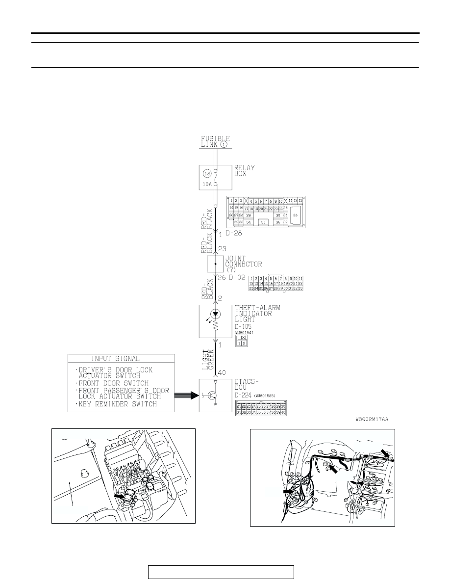
INSPECTION PROCEDURE N-1: Theft-alarm System: Theft-alarm system is not armed (theft-alarm 
indicator light does not illuminate). 

NOTE: This troubleshooting procedure requires the 
use of scan tool MB991502 and SWS monitor kit 
MB991862. For details on how to use the SWS mon-
itor, refer to "How to use SWS monitor 

P.54Ba-8

."

Theft-alarm Indicator Light Drive Circuit

ACX02274

FUSIBLE LINK (1)

AE

BATTERY

AC204170

CONNECTORS : D-02, D-28, D-105

BJ

D-28

D-105(B)

D-02

SYMPTOM PROCEDURES

TSB Revision

SWS SYMPTOM PROCEDURES

54Bb-476

.

CIRCUIT OPERATION

• When the ETACS-ECU receives a "LOCK" signal 

from the door lock actuator switch, it illuminates 
the security indicator light for approximately 18 
seconds, and then set the theft-alarm system.

• The ETACS-ECU sets the theft-alarm system 

according to the input signals from the following 
signals:

• Ignition key reminder switch: ON

• Driver's and front passenger's door switch: 

OFF

• Rear door switches: OFF

• Driver's, front passenger's and back door lock 

key cylinder switch: OFF

• Driver's, front passenger's, rear and back 

doors actuator switch: LOCK

• Hood switch: OFF

• Transmitter switch: LOCK

• Vehicle condition:

• Ignition key: Removed from the ignition key 

cylinder

• All doors: Closed

• Driver's, front passenger's and back door lock 

key cylinder: Not being operated

• Hood: Closed

• Transmitter: Turn to the "LOCK" position

.

TECHNICAL DESCRIPTION (COMMENT)
If the theft-alarm system is set normally, the input sig-
nal circuit, the "SECURITY" indicator light or the 
ETACS-ECU may be defective.

.

TROUBLESHOOTING HINTS

• The theft-alarm indicator light may be defective

• The ignition key reminder switch may be defec-

tive

• The driver's or front passenger's door switch may 

be defective

• The door switches may be defective

• The driver's, the front passenger's or the back 

door lock key cylinder switch may be defective

• The driver's, front passenger's, the rear or the 

back door lock actuator switch may be defective

• The hood switch may be defective

• The transmitter may be defective

• The ETACS-ECU may be defective

• The wiring harness or connectors may have 

loose, corroded, or damaged terminals, or termi-
nals pushed back in the connector

AC204174

CONNECTOR : D-224

D-224(B)

AG

SYMPTOM PROCEDURES

TSB Revision

SWS SYMPTOM PROCEDURES

54Bb-477

DIAGNOSIS

Required Special Tools:

• MB991223: Harness Set

• MB991502: Scan Tool (MUT-II)

• MB991862: SWS monitor kit

 STEP 1. Use scan tool MB991502 to select "ECU COMM 
CHK" on the SWS monitor display.
Check the ETACS-ECU.

CAUTION

To prevent damage to scan tool MB991502, always turn the 
ignition switch to the "LOCK" (OFF) position before con-
necting or disconnecting scan tool MB991502.
(1) Connect scan tool MB991502 to the data link connector 

(16-pin).

(2) Connect SWS monitor kit MB991862 to the data link 

connector (13-pin).

(3) Turn the ignition switch to the "LOCK" (OFF) position.
(4) Operate scan tool MB991502 according to the procedure 

below to display "ECU COMM CHK."

1. Select "SYSTEM SELECT."
2. Select "SWS."
3. Select "SWS MONITOR."
4. Select "ECU COMM CHK."

(5) Scan tool MB991502 should show "OK" on the "ECU 

COMM CHK" menu for the "ETACS ECU" menu.

Q: Is "OK" displayed on the "ETACS ECU" menu?

YES : Go to Step 2.
NO :  Refer to Inspection Procedure A-3 "Communication 

with the ETACS-ECU is not possible 

P.54Bb-25

."

AC204222AB

16-pin

13-pin

MB991502

MB991862

SYMPTOM PROCEDURES

TSB Revision

SWS SYMPTOM PROCEDURES

54Bb-478

 STEP 2. Check at ETACS-ECU connector D-224 in order to 
check the theft-alarm indicator light circuit.
(1) Disconnect ETACS-ECU connector D-224, and measure at 

the wiring harness side. 

(2) The theft-alarm indicator light should illuminate when 

terminal 40 is grounded.

Q:  Does the theft-alarm indicator light illuminate?

YES : Go to Step 9.
NO :  Go to Step 3.

 STEP 3. Check the theft-alarm indicator light.
(1) Remove the RV meter. Refer to GROUP 54A, RV meter 

P.54A-235

.

(2) Disconnect theft-alarm indicator light connector D-105.

(3) The theft-alarm indicator light should illuminate when 

battery voltage is applied between terminals 1 and 2.

Q:  Does the theft-alarm indicator light illuminate?

YES : Go to Step 4.
NO :  Replace the theft-alarm indicator light. The theft-alarm 

indicator light should illuminate, and the theft-alarm 
system should be set normally. 

AC204174

CONNECTOR : D-224

AD

D-224(B)

D-224(B)

HARNESS SIDE

21

23

24

22

32

3433

31

26

27

28

3029

38

39

40

36

37

25

35

21

22

23

24

25

26

27

28

29

30

31

32

33

34

35

36

37

38

39

40

AC100319AB

CONNECTOR D-224
(HARNESS SIDE)

AC204170

CONNECTOR : D-105

AL

HARNESS 
SIDE

D-105(B)

D-105(B)

1

2

ACX02296


Content   ..  355  356  357  358   ..