Mitsubishi Montero (2002-2004). Manual - part 356


  Index      Mitsubishi     Mitsubishi Montero - service repair manual 2002-2004 year


Search            


Content   ..  354  355  356  357   ..


Mitsubishi Montero (2002-2004). Manual - part 356


SYMPTOM PROCEDURES

TSB Revision

SWS SYMPTOM PROCEDURES

54Bb-471

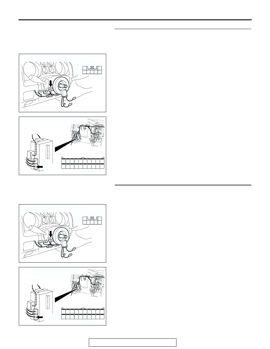
STEP 10. Check key reminder switch connector D-202 and 
ETACS-ECU connector D-224 for loose, corroded or 
damaged terminals, or terminals pushed back in the 
connector.
Q: Are key reminder switch connector D-202 and ETACS-

ECU connector D-224 in good condition?
YES : 
Go to Step 11.
NO :  Repair or replace the damaged component(s). Refer 

to GROUP 00E, Harness Connector Inspection 

P.00E-2

. Verify that the ignition key hole illumination 

light illuminates normally.

STEP 11. Check the wiring harness between key reminder 
switch connector D-202 (terminal 1) and ETACS-ECU 
connector D-224 (terminal 36).
Q: Is the wiring harness between key reminder switch 

connector D-202 (terminal 1) and ETACS-ECU connector 
D-224 (terminal 36) in good condition?
YES : 
No action is necessary and testing is complete.
NO :  The wiring harness may be damaged or the 

connector(s) may have loose, corroded or damaged 
terminals, or terminals pushed back in the connector. 
Repair the wiring harness as necessary. Verify that 
the ignition key hole illumination light illuminates 
normally.

AC204172

CONNECTOR : D-202

AB

HARNESS SIDE

4

5

3

1

6

7

2

D-203

AC204174

CONNECTOR : D-224

AD

D-224(B)

D-224(B)

HARNESS SIDE

21

23

24

22

32

3433

31

26

27

28

3029

38

39

40

36

37

25

35

AC204172

CONNECTOR : D-202

AB

HARNESS SIDE

4

5

3

1

6

7

2

D-203

AC204174

CONNECTOR : D-224

AD

D-224(B)

D-224(B)

HARNESS SIDE

21

23

24

22

32

3433

31

26

27

28

3029

38

39

40

36

37

25

35

SYMPTOM PROCEDURES

TSB Revision

SWS SYMPTOM PROCEDURES

54Bb-472

THEFT-ALARM SYSTEM

GENERAL DESCRIPTION CONCERNING THE THEFT-ALARM SYSTEM

M1549022100047

The following ECUs affect the functions and control 
of the theft-alarm function.

Theft-alarm system

.

Arming the system
After the following procedures have been completed, 
the theft-alarm indicator light illuminates for about 20 
seconds. When the light goes off, the system is 
armed.

1. Pull out the ignition key from the key cylinder.
2. Lock all doors with the key or the RKE transmit-

ter.

NOTE: The system is set regardless of whether the 
hood trunk is open or closed, and is armed as soon 
as the light goes off.

.

Disarming the system
The system is disarmed if any of the following condi-
tions is satisfied.

• Unlock the doors by using the door lock key cylin-

der.

• Unlock the doors by using the RKE transmitter.

.

Activating the alarm

1. If any door or hood is opened without key or RKE 

transmitter, while the system is armed, the horn 
(theft-alarm horn and horn) will sound intermit-
tently and the headlights (high-beam) will flash on 
and off for approximately three minutes.

2. If any door or the hood is opened without disarm-

ing the alarm by using the key or the RKE trans-
mitter, the alarm will be activated again. Note that 
the alarm will not be deactivated by disconnect-
ing the battery.

.

Deactivating the alarm
To deactivate the alarm, insert the key into the door’s 
key cylinder and turn the key or operate the RKE 
transmitter (except "PANIC" button).

.

Checking the system operation
The activation/operation of the system can be 
checked by following steps below.

1. Turn the ignition key to the "ON" position and to 

fully open the window on the driver’s side with the 
power window switch.

2. Turn the ignition key to the "LOCK" (OFF) posi-

tion and then remove the key from the ignition.

3. Close all doors.
4. Lock all doors with the key or RKE transmitter.
5. The theft-alarm indicator light will illuminate; 

check to be sure that the light goes off in about 20 
seconds.

6. After the theft-alarm indicator light goes off, 

unlock with the driver’s door lock knob, and open 
the driver’s door.

7. Check to be sure that, when the door is opened, 

the horn starts sounding and the headlights flash 
on and off.

8. To stop the alarm, insert the key into the door key 

cylinder and turn the key or press RKE transmit-
ter switch.

NOTE: To check the alarm for the opening of the 
hood, open the hood by using the hood release lever, 
located on the driver’s side either before the alarm is 
activated by the opening of a door, or after the finish 
of the first three-minute alarm.

FUNCTION

CONTROL ECU

Theft-alarm system

ETACS-ECU, front-ECU

SYMPTOM PROCEDURES

TSB Revision

SWS SYMPTOM PROCEDURES

54Bb-473

General circuit diagram for the theft-alarm

SYMPTOM PROCEDURES

TSB Revision

SWS SYMPTOM PROCEDURES

54Bb-474


Content   ..  354  355  356  357   ..