Mitsubishi Montero (2002-2004). Manual - part 285


  Index      Mitsubishi     Mitsubishi Montero - service repair manual 2002-2004 year


Search            


Content   ..  283  284  285  286   ..


Mitsubishi Montero (2002-2004). Manual - part 285


SYMPTOM PROCEDURES

TSB Revision

SWS SYMPTOM PROCEDURES

54Bb-187

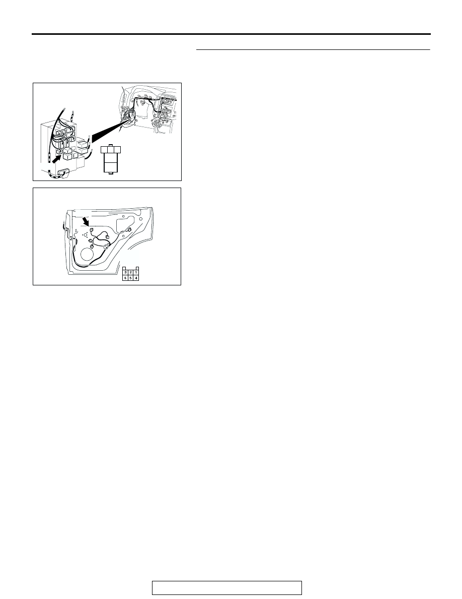
STEP 38. Check the harness wiring between power 
window relay connector D-219 (terminal 4) and rear power 
window sub-switch (RH) connector H-19 (terminal 4).

AC203850AB

CONNECTOR: D-219

JUNCTION BLOCK 
(FRONT VIEW)

D-219

1

2

3

4

5

JUNCTION 
BLOCK SIDE

D-219

AC000316 AE

H-19

CONNECTOR: H-19

REAR DOOR<RH>

(HARNESS SIDE)

H-19

SYMPTOM PROCEDURES

TSB Revision

SWS SYMPTOM PROCEDURES

54Bb-188

NOTE: Also check junction block connector D-208 and inter-
mediate connectors D-111 and F-23. If junction block connector 
D-208, intermediate connector D-111 or F-23 is damaged, 
repair or replace the connector as described in GROUP 00E, 
Harness Connector Inspection 

P.00E-2

.

Q: Is the harness wiring between power window relay 

connector (terminal 4) and rear power window sub-
switch (RH) connector H-19 (terminal 4) in good 
condition?
YES : 
No action is necessary and testing is complete.
NO :  The wiring harness may be damaged or the 

connector(s) may have loose, corroded or damaged 
terminals, or terminals pushed back in the connector. 
Repair the wiring harness as necessary. Verify that 
the rear power window sub-switch (RH) should now 
work normally.

AC203850AD

CONNECTOR: D-208

JUNCTION BLOCK 
(FRONT VIEW)

D-208

D-208

1

2

3 4 5 6

AC203860AC

D-111

CONNECTOR: D-111

D-111

AC204484

AE

F-23

F-23

CONNECTORS: F-12, F-23

F-12

F-12

SYMPTOM PROCEDURES

TSB Revision

SWS SYMPTOM PROCEDURES

54Bb-189

STEP 39. Check at rear power window sub-switch (RH) 
connector H-19 in order to check the ground circuit to the 
rear power window sub-switch (RH).
(1) Disconnect rear power window sub-switch (RH) connector 

H-19, and measure at the harness side.

(2) Measure the resistance value between terminal 5 and 

ground.

• The resistance should measure 2 ohms or less.

Q: Is the measured resistance 2 ohms or less?

YES : Go to Step 43.
NO :  Go to Step 40.

STEP 40. Check power window main switch connector H-
05 and rear power window sub-switch (RH) connector H-19 
for loose, corroded or damaged terminals, or terminals 
pushed back in the connector.
Q: Are power window main switch connector H-05 and rear 

power window sub-switch (RH) connector H-19 in good 
condition?
YES : 
Go to Step 41.
NO :  Repair or replace the damaged component(s). Refer 

to GROUP 00E, Harness Connector Inspection 

P.00E-2

Verify that the rear power window sub-

switch (RH) should now work normally.

AC204323

1

2

3

4

5

6

AF

CONNECTOR H-19
(HARNESS SIDE)

AC203774

CONNECTOR: H-05

AE

DRIVER'S DOOR

H-05

H-05

AC000316 AD

H-19

CONNECTOR: H-19

REAR DOOR<RH>

H-19

SYMPTOM PROCEDURES

TSB Revision

SWS SYMPTOM PROCEDURES

54Bb-190

STEP 41. Check the harness wiring between power 
window main switch connector H-05 (terminal 2) and rear 
power window sub-switch (RH) connector H-19 (terminal 
5).

AC203774

CONNECTOR: H-05

AF

DRIVER'S DOOR

H-05

H-05

(HARNESS SIDE)

AC000316 AE

H-19

CONNECTOR: H-19

REAR DOOR<RH>

(HARNESS SIDE)

H-19


Content   ..  283  284  285  286   ..